Assembling Infrared Touch Control Module

a technology of infrared touch and control module, which is applied in the direction of optical radiation measurement, instruments, material analysis, etc., can solve the problem of higher cos

Inactive Publication Date: 2014-09-18
TOP VICTORY INVESTMENTS
View PDF3 Cites 10 Cited by
  • Summary
  • Abstract
  • Description
  • Claims
  • Application Information

AI Technical Summary

Benefits of technology

The invention is an assembling infrared touch control module that can be adapted to different sizes of display devices. It includes four L-shaped frame members with infrared transmitter / receiver components and connectors for assembly. The module can be assembled to form a frame of any size, and the infrared transmitter / receiver components provide an active touch area for the frame. The module also includes a program for checking the assembly and setting the infrared transmitter / receiver components. The invention allows for easy customization and flexibility in the size of the touch control module for different display devices.

Problems solved by technology

However, each infrared touch control module is designed to have a frame of a fixed size to be adapted to a corresponding display device of a specific size, and an active touch area of the infrared touch control module is designed to be within an active display area of the display device so that the range of the active touch area is not adjustable.
Display devices of different sizes need infrared touch control modules having frames of different sizes so as to need many molds of the frames and result in higher cost.

Method used


Image

  • Assembling Infrared Touch Control Module
  • Assembling Infrared Touch Control Module
  • Assembling Infrared Touch Control Module

Examples


Embodiment Construction

[0024]Reference will now be made in detail to the preferred embodiments of the invention, examples of which are illustrated in the accompanying drawings. Wherever possible, the same reference numbers are used in the drawings and the description to refer to the same or like parts.

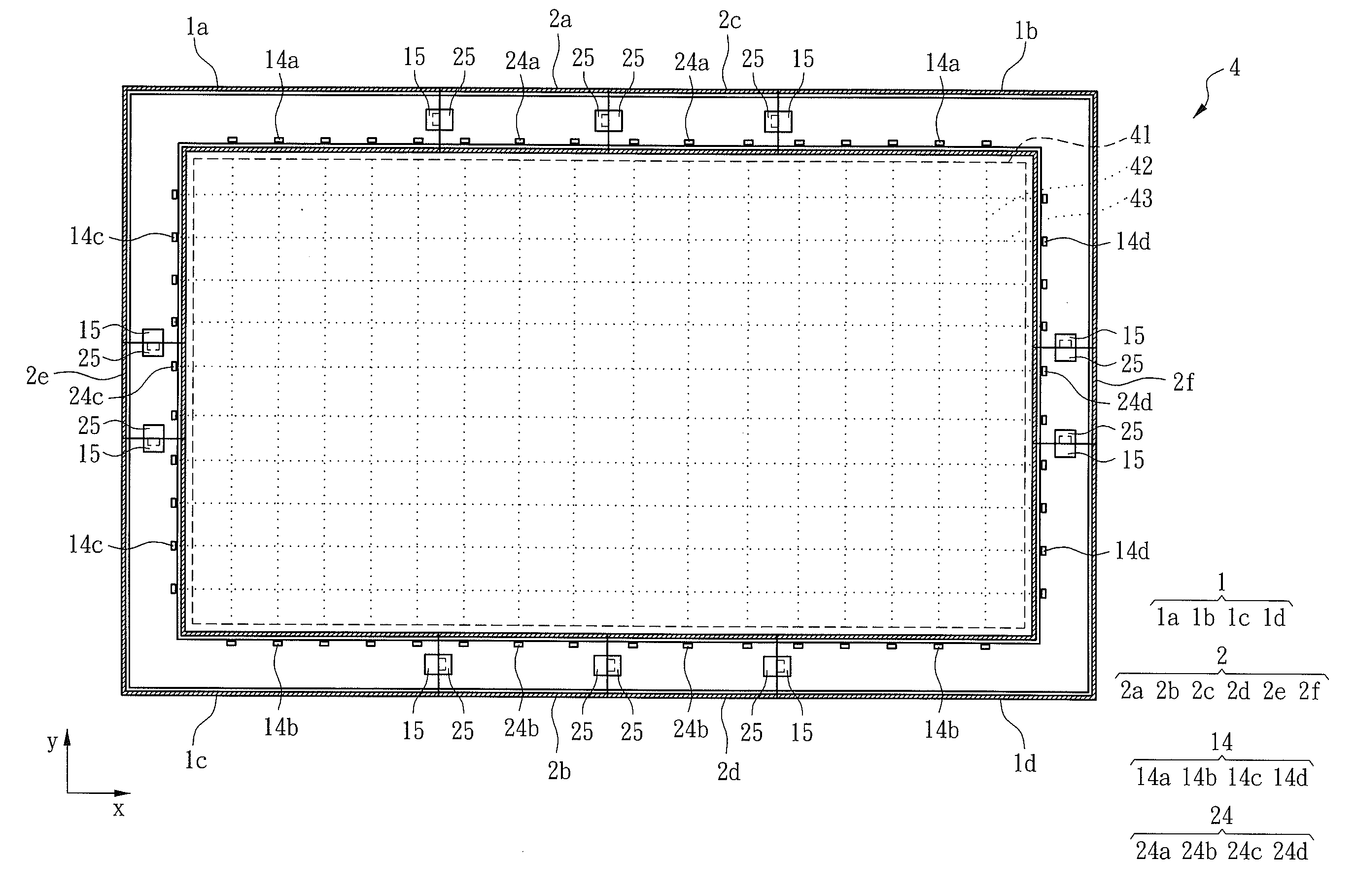
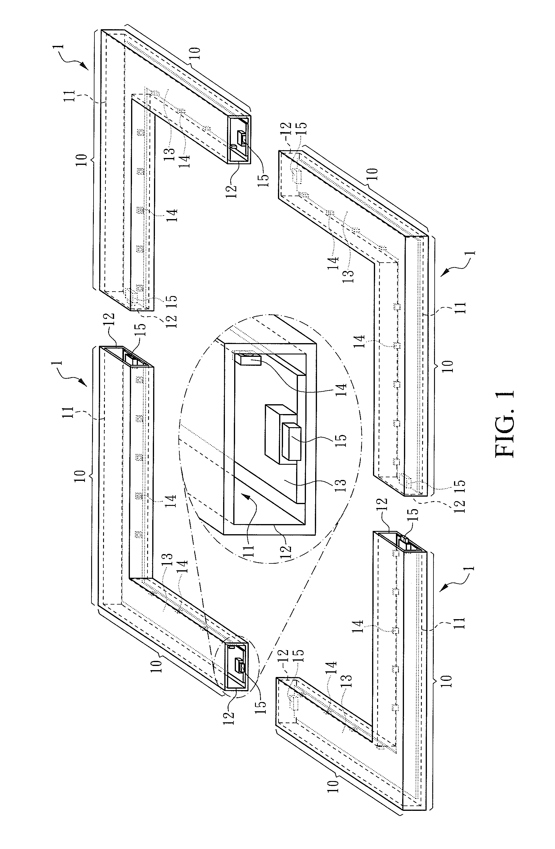
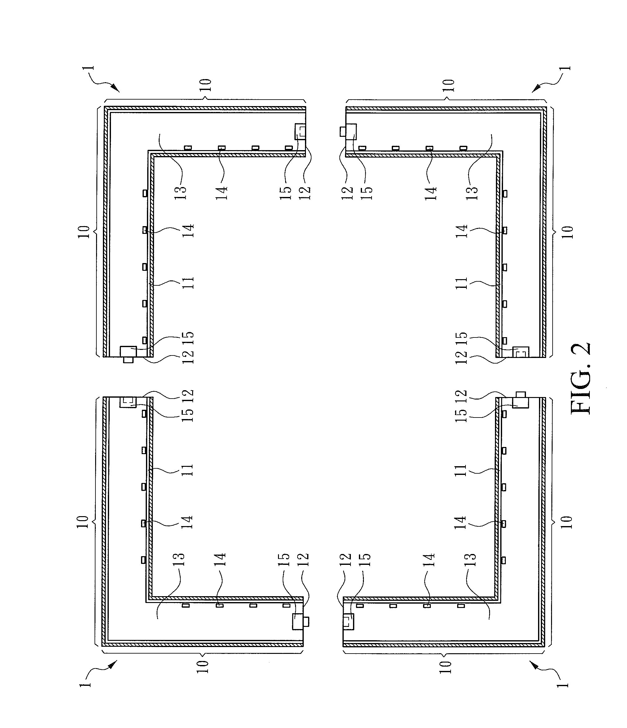
[0025]FIG. 1 is an exploded view of an assembling infrared touch control module according to an embodiment of the invention, and FIG. 2 is a cross-sectional top plan view of the assembling infrared touch control module shown in FIG. 1. Referring to FIGS. 1 and 2, an assembling infrared touch control module includes four L-shaped first frame members 1. Each first frame member 1 has two arms 10, and each arm 10 has a free end and a connected end, in which the connected ends of the two arms 10 are connected to each other, and the two arms 10 are perpendicular to each other so as to form the “L-shaped” first frame member 1. Each first frame member 1 has a first space 11 and two first openings 12 in communication...


PUM


Abstract

An assembling infrared touch control module is provided and includes four L-shaped first frame members and a plurality of straight second frame members matched in pairs. Each first and second frame member has a space therein and two openings at two ends thereof, respectively, in communication with the space. Each space has a circuit board therein. Each circuit board has a plurality of infrared transmitter / receiver components thereon and two connectors thereon at the two openings, respectively. The four first frame members and the second frame members whose number may be increased or decreased by demand are assembled together to form a frame by means of the connectors so that an active touch area of the frame may be resized by demand to be adapted to a display device of any size, and an additional touch control function adapted to an extended area for the display device may be set.

Description

BACKGROUND OF THE INVENTION[0001]1. Field of the Invention[0002]The invention relates to an infrared touch control module. More particularly, the invention relates to an assembling infrared touch control module.[0003]2. Description of Related Art[0004]Nowadays, many display devices employ built-in or add-on infrared touch control modules. The infrared touch control module provides a touch control function on the screen of the display device and may further provide another touch control function about the setting of the display device such as voice volume, color contrast or brightness to take the place of conventional physical keys disposed on the front frame of the display device so as to allow more different appearance designs to be made in the front frame. However, each infrared touch control module is designed to have a frame of a fixed size to be adapted to a corresponding display device of a specific size, and an active touch area of the infrared touch control module is designe...

Claims


Application Information

Patent Timeline
IPC IPC(8): G06F3/042
CPCG06F3/0421
Inventor HUNG, IMANLIN, CHIEN-TAHUANG, ERICCHEN, SEAN
Owner TOP VICTORY INVESTMENTS
Why Eureka
Try Eureka