Floating gate memory cells in vertical memory

Active Publication Date: 2014-09-18
MICRON TECH INC
View PDF2 Cites 63 Cited by
  • Summary
  • Abstract
  • Description
  • Claims
  • Application Information

AI Technical Summary

Problems solved by technology

Volatile memory devices lose data stored therein when the power supply is interrupted.
For example, power may not be available.
In some cases, the structures illustrated in FIGS. 2A-P and FIGS. 3A-D may be susceptible to a potentially negative condition.
However, even when the nitride layer 350 is relatively thick, charge leakage may still

Method used


Image

  • Floating gate memory cells in vertical memory
  • Floating gate memory cells in vertical memory
  • Floating gate memory cells in vertical memory

Examples


Embodiment Construction

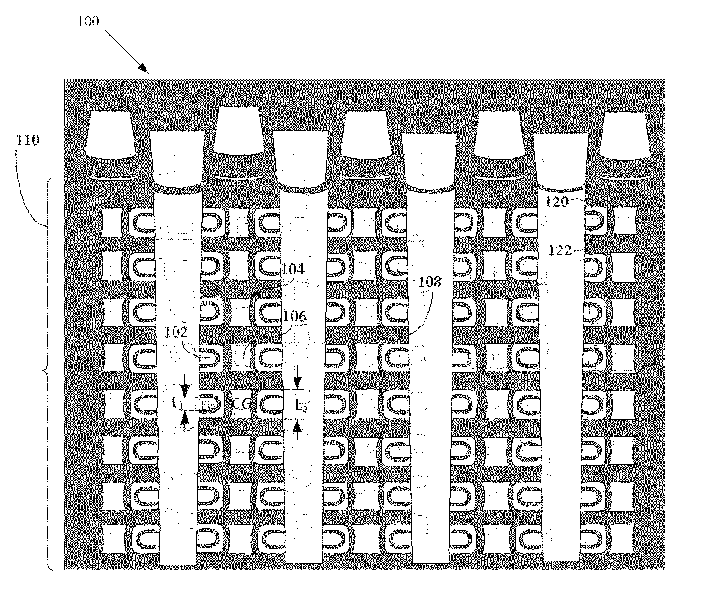
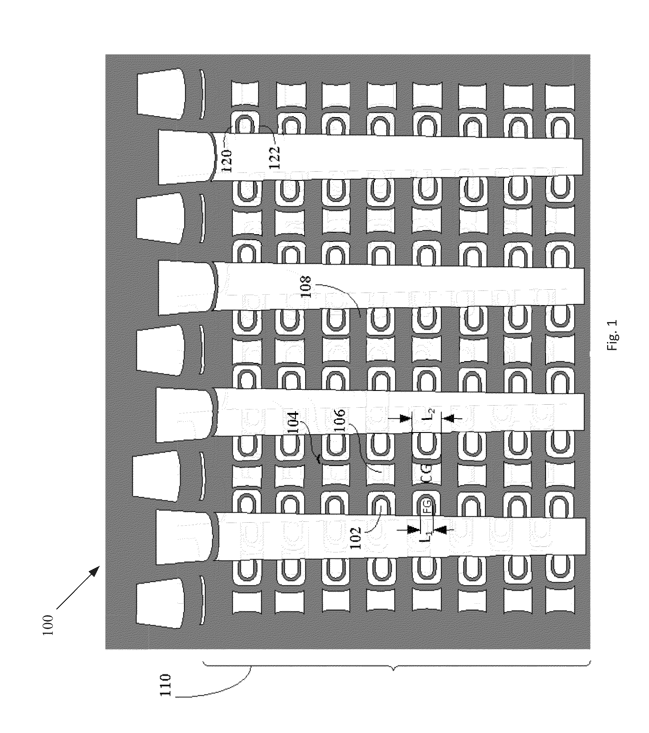
[0013]FIG. 1 illustrates an example of a vertical memory 100 that includes vertical strings of memory cells in a 3D NAND (Not And) architecture, according to what the inventors consider to be a prior internal embodiment. The vertical memory 100 includes a stack of memory cells 110 that includes floating gates (FGs) 102, charge blocking structures (e.g., IPD 104), control gates (CGs) 106, and tiers of dielectric material (e.g., oxide layers 108). In the illustrated example, IPD 104 is disposed between each floating gate (FG) 102 and control gate (CG) 106. Charge can get trapped on portions of the IPD 104, such as on portions of the IPD 104 that laterally extend between a FG 102 and respective tiers of dielectric material. As shown in FIG. 1, the length of a FG 102, i.e., L1, is approximately half of the length of a respective CG 106, i.e., L2. In one embodiment, for example, the length of a FG 102 in the direction of current flow (e.g., in a pillar of a string of the memory cells) is...


PUM


Abstract

Floating gate memory cells in vertical memory. A control gate is formed between a first tier of dielectric material and a second tier of dielectric material. A floating gate is formed between the first tier of dielectric material and the second tier of dielectric material, wherein the floating gate includes a protrusion extending towards the control gate. A charge blocking structure is formed between the floating gate and the control gate, wherein at least a portion of the charge blocking structure wraps around the protrusion.

Description

BACKGROUND[0001]Semiconductor memory devices that are used for storing data can generally be divided into two classes: volatile memory devices and non-volatile memory devices. Volatile memory devices lose data stored therein when the power supply is interrupted. In contrast, non-volatile memory devices retain the stored data even when the power supply is interrupted. Therefore, nonvolatile memory devices, such as flash memory devices, are widely used in applications where power may be interrupted. For example, power may not be available. Power may occasionally be interrupted or a lower power consumption may be dictated, e.g., in a mobile phone system, a memory card for storing music and / or movie data. With increasing process capability and miniaturization, there is an increased demand for memory cells of a smaller size, even in the flash memory device.BRIEF DESCRIPTION OF THE DRAWINGS[0002]In the drawings, which are not necessarily drawn to scale, like numerals may describe similar ...

Claims


Application Information

Patent Timeline
IPC IPC(8): H01L29/788
CPCH01L29/788H01L29/40114H01L29/66825H10B41/27H01L29/66833H01L2924/1438H10B43/20H01L29/66666
Inventor DENNISON, CHARLES H.GODA, AKIRAHOPKINSSIMSEK-EGE, FATMA ARZUMPARAT, KRISHNA K.
Owner MICRON TECH INC
Why Eureka
Try Eureka