Methods and devices relating to capacitive micromachined diaphragms and transducers

a micro-machined diaphragm and capacitive technology, applied in the field of micro-electromechanical systems, can solve the problems of essentially impossible and the inability to implement the cmt built using sic structural membranes

Inactive Publication Date: 2014-09-18
MCGILL UNIV
View PDF3 Cites 17 Cited by
  • Summary
  • Abstract
  • Description
  • Claims
  • Application Information

AI Technical Summary

Benefits of technology

[0008]It is an object of the present invention to address limitations of the prior art relating to microelectromechanical systems and more particularly to capacitive micromachined diaphragms, transducers, and ultrasonic transducers.

Problems solved by technology

This would be essentially impossible if each element were to be connected to the IC with wire bonds.
However, to the inventor's knowledge, CMT built using SiC structural membranes have not been implemented.

Method used


Image

  • Methods and devices relating to capacitive micromachined diaphragms and transducers
  • Methods and devices relating to capacitive micromachined diaphragms and transducers
  • Methods and devices relating to capacitive micromachined diaphragms and transducers

Examples


Embodiment Construction

[0043]The present invention is directed to microelectromechanical systems and more particularly to capacitive micromachined diaphragms, transducers, and ultrasonic transducers.

[0044]The ensuing description provides exemplary embodiment(s) only, and is not intended to limit the scope, applicability or configuration of the disclosure. Rather, the ensuing description of the exemplary embodiment(s) will provide those skilled in the art with an enabling description for implementing an exemplary embodiment. It being understood that various changes may be made in the function and arrangement of elements without departing from the spirit and scope as set forth in the appended claims.

[0045]A. Device Fabrication

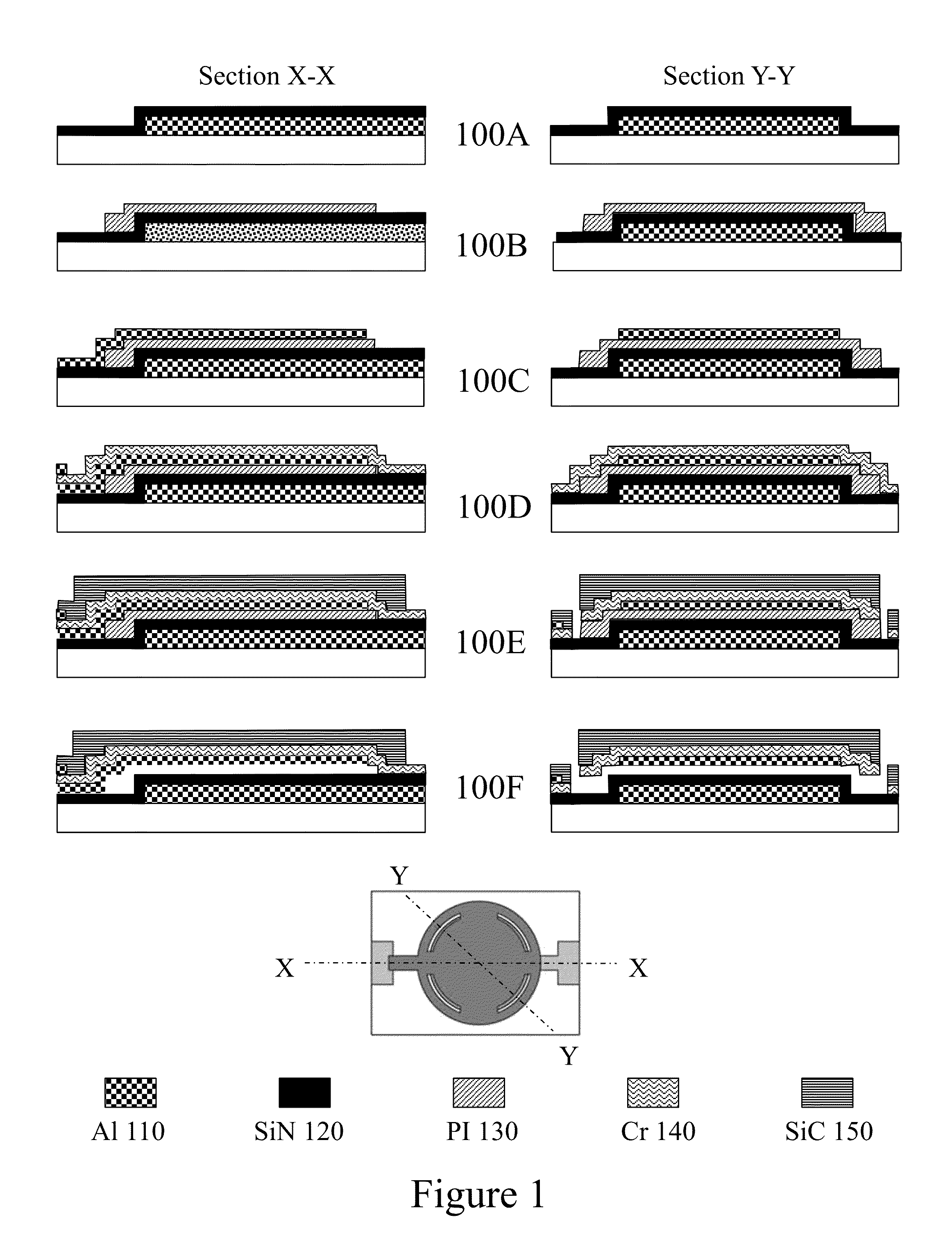
[0046]A.1 Process Flow: Referring to FIG. 1 first to sixth process steps 100A to 100F respectively with respect to manufacturing a CMT according to an embodiment of the invention are depicted exploiting a 5-mask technology process. The process begins for example with a 150 mm silicon s...


PUM


Abstract

Monolithically integrated capacitive micromachined transducers (CMTs) offer combined process steps, shared layers, simplified packaging, and reduced die size by overlapping the CMTs with the integrated circuit (IC) electronics. Moreover, a CMT array directly above the electronics also allows for varying the excitation signal phase to each CMT element thereby enabling beam-forming techniques. Above-IC integration is particularly attractive by not requiring any alteration of the semiconductor fabrication process and allowing subsequent implementation independent of IC fabrication. Naturally, this scheme requires that the CMT technology limit itself to IC compatible materials and chemicals, as well as process step temperatures within a specific thermal budget. Embodiments of the invention expanding upon surface micromachining technology allow the fabrication of IC-compatible CMT structures with superior mechanical properties and resistance to harsh environments such as high temperature, corrosive media and high-g shocks, by exploiting silicon carbide (SiC) structures to form the upper CMT structural layer.

Description

CROSS-REFERENCE TO RELATED APPLICATIONS[0001]This patent application claims the benefit of U.S. Provisional Patent Application US 61 / 781,886 filed Mar. 14, 2013 entitled “Methods and Devices relating to Capacitive Micromachined Diaphragms and Transducers.”FIELD OF THE INVENTION[0002]This invention relates to microelectromechanical systems and more particularly to capacitive micromachined diaphragms, transducers, and ultrasonic transducers.BACKGROUND OF THE INVENTION[0003]Over the past 20 years there has been intensive research on capacitive micromachined transducers (CMT), including capacitive micromachined ultrasonic transducers (CMUT), as compared with piezoelectric transducers (PZT), the lower mechanical impedance of CMT membranes offers the potential for a better impedance match with fluid media. Examples of CMT devices within the prior art include for example Chen et al in “Design and characterization of an air-coupled capacitive ultrasonic sensor fabricated in a CMOS process” ...

Claims


Application Information

Patent Timeline
Patent Type & Authority Applications(United States)
IPC IPC(8): G10K9/12
CPCG10K9/12B06B1/0292
Inventor EL-GAMAL, MOURADZHANG, QINGCICEK, PAUL-VAHENABKI, FREDERIC
Owner MCGILL UNIV
Why Eureka
Try Eureka