
Facility lighting control system

a lighting control system and control system technology, applied in lighting apparatus, light sources, instruments, etc., can solve the problems of high operating costs of the system, and achieve the effect of recovering revenu

Inactive Publication Date: 2014-09-18
HOWARD INDS
View PDF5 Cites 2 Cited by
  • Summary
  • Abstract
  • Description
  • Claims
  • Application Information

AI Technical Summary

Benefits of technology

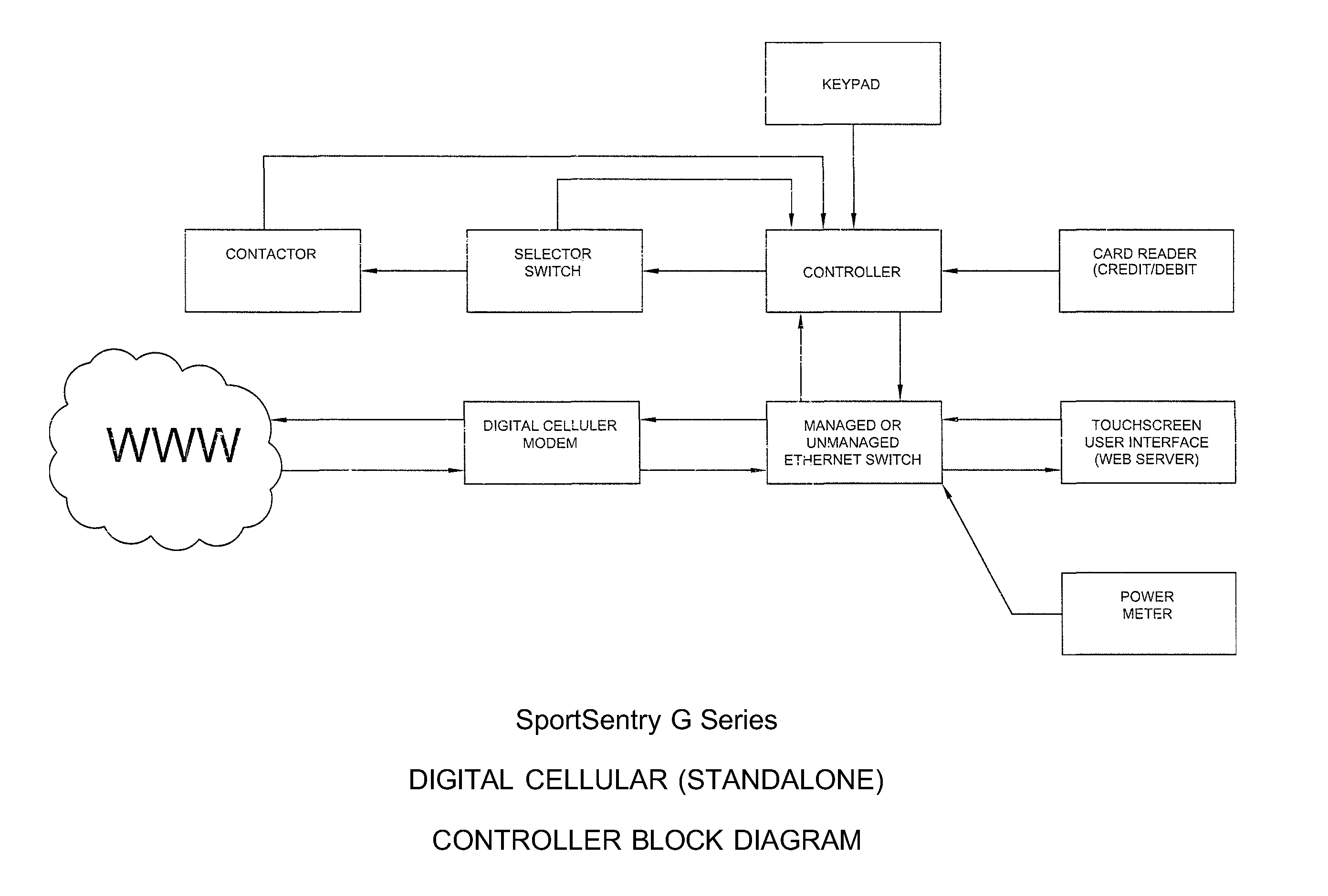
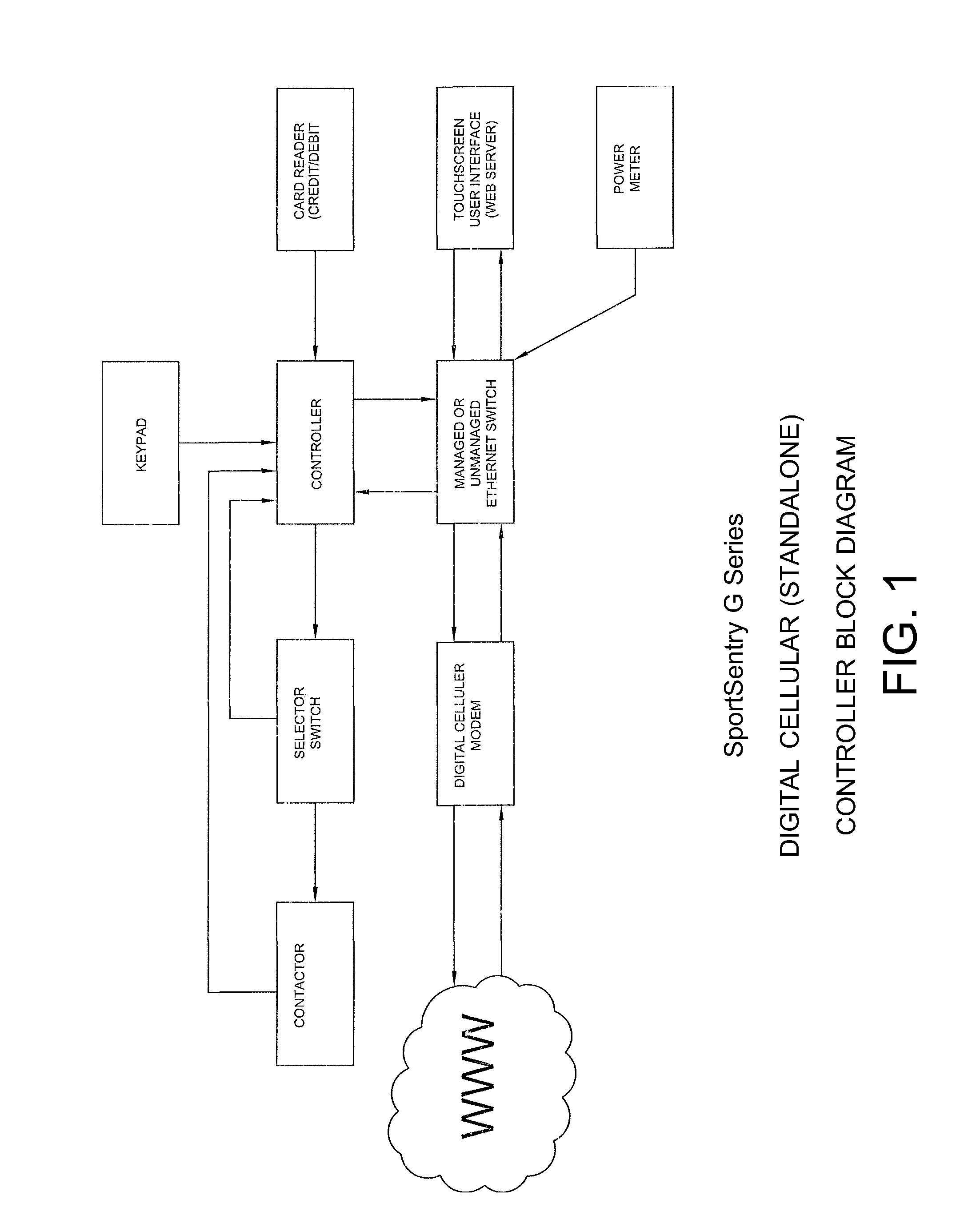
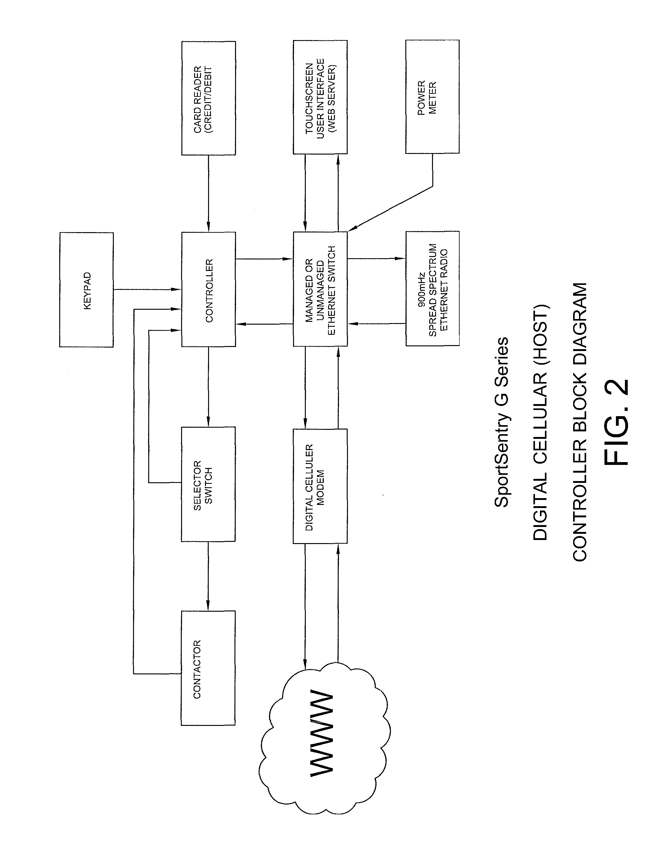
The patent describes a sports lighting control system that allows facilities operators to recover revenue by using debit / credit cards, prepaid cards, or a purchased key code. The system also controls time of day and unauthorized usage, and can notify the owners of usage outside of the normal operating hours via email or text messaging. The system can be used at various sports facilities and can control all aspects of lighting within a park including parking lots and walking trails.

Problems solved by technology

As a result, the costs of operating the system can be high.
Other known systems require the user to log on to a specific website to make changes to schedules, override and monitor their own facilities, but typically do not allow for public based access for local, remote or “pay for play.” The current technology requires that each controller in a facility that requires multiple control units have cellular communications at each controller to communicate with the system.

Method used


Image

  • Facility lighting control system
  • Facility lighting control system
  • Facility lighting control system

Examples


Embodiment Construction

[0012]The following detailed description is presented to enable any person skilled in the art to make and use the invention. For purposes of explanation, specific details are set forth to provide a thorough understanding of the present invention. However, it will be apparent to one skilled in the art that these specific details are not required to practice the invention. Descriptions of specific applications are provided only as representative examples. Various modifications to the preferred embodiments will be readily apparent to one skilled in the art, and the general principles defined herein may be applied to other embodiments and applications without departing from the scope of the invention. The present invention is not intended to be limited to the embodiments shown, but is to be accorded the widest possible scope consistent with the principles and features disclosed herein.

[0013]The invention claimed herein allows both facilities operator and the public to access the interfa...


PUM


Abstract

A lighting control system for municipalities and recreation departments is disclosed. The lighting system can process payments so that a user can pay for usage of a recreational facility at the time of need. The lighting control system can communicate with remote systems such that only a single cellular connection or broadband connection is required.

Description

CROSS-REFERENCES TO RELATED APPLICATIONS[0001]This application claims the benefit of U.S. Provisional Application No. 61 / 792,670, filed Mar. 15, 2013, which is incorporated herein by reference in its entirety.FIELD OF THE INVENTION[0002]The present invention is generally directed toward a system for controlling a lighting system for a recreational facility.BACKGROUND OF THE INVENTION[0003]Lighting control systems are used to assist parks and recreation departments and other municipality departments with monitoring, regulating, and charging for usage of parks, tennis courts, and other recreational facilities. The systems that are currently available require a cellular broadband connection or internet connection to communicate at each of the parks. As a result, the costs of operating the system can be high.[0004]Other known systems require the user to log on to a specific website to make changes to schedules, override and monitor their own facilities, but typically do not allow for pu...

Claims


Application Information

Patent Timeline
Patent Type & Authority Applications(United States)
IPC IPC(8): H05B37/02
CPCH05B37/0209H05B47/19
Inventor INZER, MARSHALL CLAUDEROCHESTER, MICHAEL CHANDLER
Owner HOWARD INDS
Learn More