Security system health monitoring

a security system and health monitoring technology, applied in the field of premises-based systems, can solve the problems of high installation and maintenance complexity of security systems, intrusion, fire, carbon monoxide, etc., and achieve the effect of reducing the complexity of installation and maintenance, reducing the risk of fire, and improving the safety of security systems

Active Publication Date: 2014-09-18
ADT US HLDG INC
View PDF12 Cites 136 Cited by
  • Summary
  • Abstract
  • Description
  • Claims
  • Application Information

AI Technical Summary

Benefits of technology

[0007]The invention advantageously provides a method and system for premises-based systems that centrally control a plurality of separate devices, and in particular to monitor health of the premises-based system to confirm operation.

Problems solved by technology

Such hazards and threats include intrusion, fire, carbon monoxide and flooding, among others dangers that may be monitored and reported to a monitoring station.
Installation and servicing complexity associated with these systems tends to be high, as an installer has to physically position, mount, and configure the control panel and all of the various sensors, while taking into account a variety of performance characteristics and requirements for each device to ensure proper operation of the system.
These systems also typically incorporate a manufacturer's specific technology designed for the manufacturer's security application, and only certain devices may only appropriately interoperate with other devices in certain ways.
However, these existing security systems suffer from the same problem, namely, a lack of health monitoring of the security system.
In particular, these existing security systems only generate a system alert when the health levels of sensors or components fall below predefined minimum thresholds.
In other words, health level thresholds in existing systems are only triggered when the levels are so bad such that at least one sensor or component of the system stops functioning properly.
Further, customers have no way of knowing when the heath levels of their security systems are going to degrade to the point that functionality, i.e., monitoring capabilities, of the security system are affected.
Such a failure may come at an inopportune time such as when the customer is on vacation or otherwise away from the premise.
Therefore, the user is not able to fix the problem, e.g., change batteries, or call for a service technician because the customer may not even know a problem exist until the customer returns to the premise.
Such a sudden failure in monitoring capabilities of these existing security systems may inadvertently provide thieves the window of opportunity they have been waiting for.

Method used


Image

  • Security system health monitoring
  • Security system health monitoring
  • Security system health monitoring

Examples


Embodiment Construction

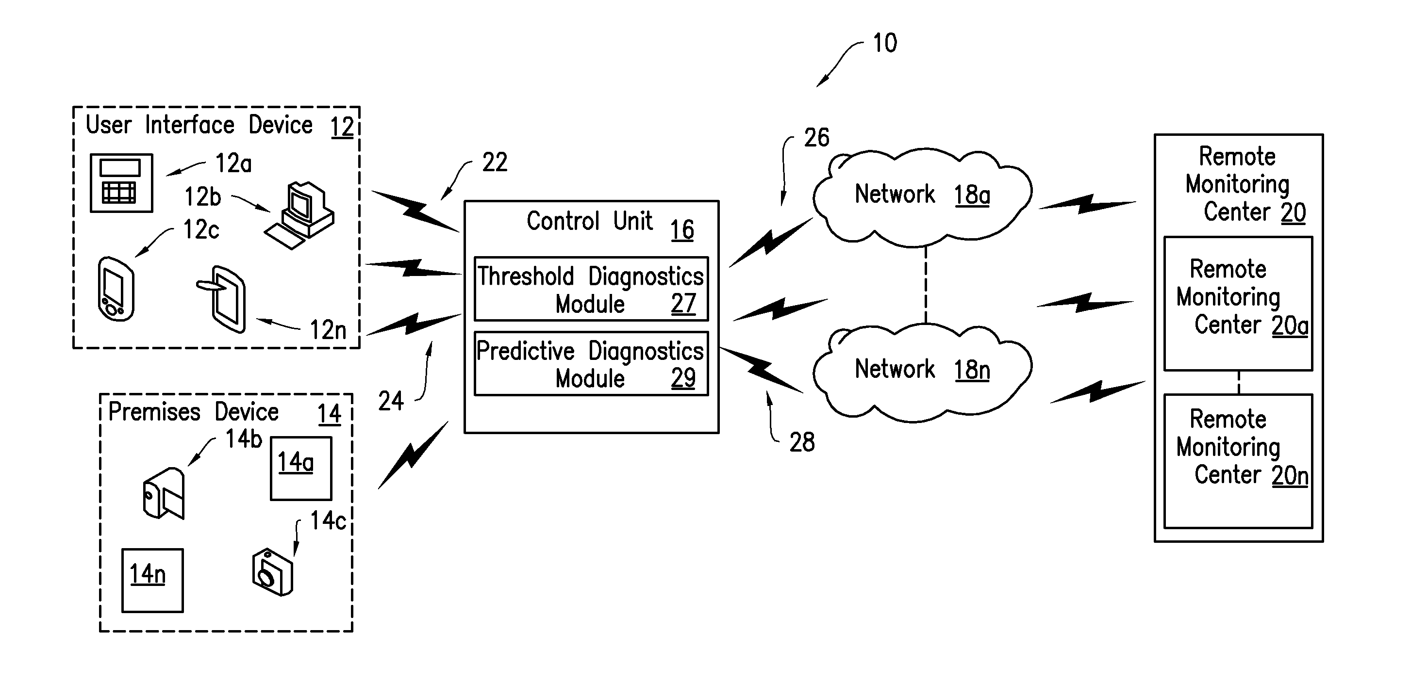
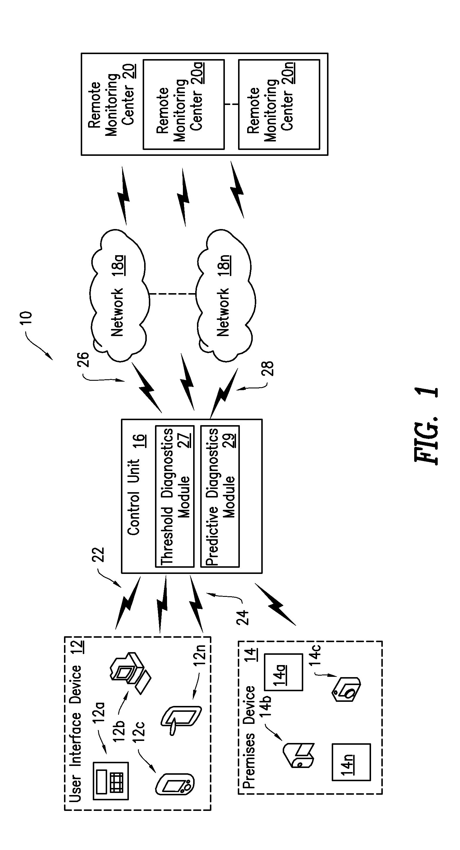
[0027]The invention advantageously provides a system, device and method for a premises based control system health management. Accordingly, the system, device and method components have been represented where appropriate by convention symbols in the drawings, showing only those specific details that are pertinent to understanding the embodiments of the invention so as not to obscure the disclosure with details that will be readily apparent to those of ordinary skill in the art having the benefit of the description herein. While the invention is described herein with respect to a security system, the invention is not limited to such. It is contemplated that the processes and functions described herein may be applied to any premises based system that centrally controls a plurality of separate devices.

[0028]As used herein, relational terms, such as “first” and “second,”“top” and “bottom,” and the like, may be used solely to distinguish one entity or element from another entity or eleme...


PUM


Abstract

An apparatus and method for determining at least one operational condition of a premises based system including at least one premises device. The apparatus includes a processor configured to perform a diagnostic procedure. The diagnostic procedure includes determining operational data of the premises based system, the operational data indicating at least one of a premises device and the apparatus is operating outside a failure range and performing predictive analysis based at least in part on the received operational data. The predictive analysis indicates whether the at least one of premises device and apparatus is likely to operate within the failure range within a predefined period of time. The diagnostic procedure includes causing a notification alert to be transmitted to at least one of a user interface device and remote monitoring center based on the predictive analysis.

Description

CROSS-REFERENCE TO RELATED APPLICATION[0001]This application is related to and claims priority to U.S. Provisional Patent Application Ser. No. 61 / 788,924, filed Mar. 15, 2013, entitled “SECURITY SYSTEM HEALTH MONITORING”, the entirety of which is incorporated herein by reference.FIELD OF THE INVENTION[0002]The invention relates to premises-based systems that centrally control a plurality of separate devices, and in particular to monitoring health of the premises-based system to confirm operation.BACKGROUND OF THE INVENTION[0003]The demand for systems that use a variety of devices at a location to monitor a variety of conditions, such as monitoring homes and businesses for alarm conditions, allowing users to centrally control various devices (such as thermostats, switches, cameras, appliances, etc.), monitor medical conditions, and the like has continued to grow as more home and business owners seek better control over their premises and to protect it from various hazards and threats...

Claims


Application Information

Patent Timeline
Patent Type & Authority Applications(United States)
IPC IPC(8): G08B29/14
CPCG08B29/14G05B23/0232G05B23/0235G05B23/0272G05B23/0283G06F1/30G06F1/3234G08B29/04
Inventor SHAPIRO, STEVENNORTH, RAYMONDRADER, TIMOTHY ALBERTPERDOMO, JORGEROUSE, ANNE-MARIEBLACK, JAMES TIMOTHY
Owner ADT US HLDG INC
Why Eureka
Try Eureka