
Hierarchical image classification system

a classification system and hierarchy technology, applied in image analysis, image enhancement, instruments, etc., can solve the problems of preventing the generation of valid homographies, pixel-based template matching is very time-consuming and computationally expensive, and the matching scheme is far more computationally expensiv

Inactive Publication Date: 2014-09-18
SHARP LAB OF AMERICA INC
View PDF11 Cites 27 Cited by
  • Summary
  • Abstract
  • Description
  • Claims
  • Application Information

AI Technical Summary

Benefits of technology

The present invention relates to a hierarchical classification system and a defect detection system for images. The invention aims to provide a computationally efficient classification and defect detection technique that can handle large amounts of data and detect defects accurately. The invention uses various techniques such as template matching, feature point based alignment, and sliding window based classification to achieve this goal. The invention also takes into account the challenges of detecting defects in images, such as the difficulty of gathering training samples with labeled defect masks and the high intra-class and inter-class variance of potential defects. The invention proposes a solution to address these challenges and provide a more reliable and efficient method for defect detection in images.

Problems solved by technology

In these situations, too many ambiguous matches prevents generating a valid homography.
Pixel-based template matching is very time-consuming and computationally expensive.
When searching for an object with arbitrary orientation, one technique is to do template matching with the model image rotated in every possible orientation, which makes the matching scheme far more computationally expensive.
However, often it is difficult to gather a reasonable size of training samples with labeled defect masks, which requires cumbersome manual annotation.
Labeling by human operators leads to severe waste of resources to produce such samples, especially given that new datasets and defects periodically arise.
Given the high intra-class and inter-class variance of potential defects, designing suitable features tends to be problematic.
Saliency detection typically estimates coarse and subjective saliency support on natural images, and often leads to severe over detections while making a number of assumptions in the process.
The anomaly detection process is not suitable for large sized defects.

Method used


Image

  • Hierarchical image classification system
  • Hierarchical image classification system
  • Hierarchical image classification system

Examples


Embodiment Construction

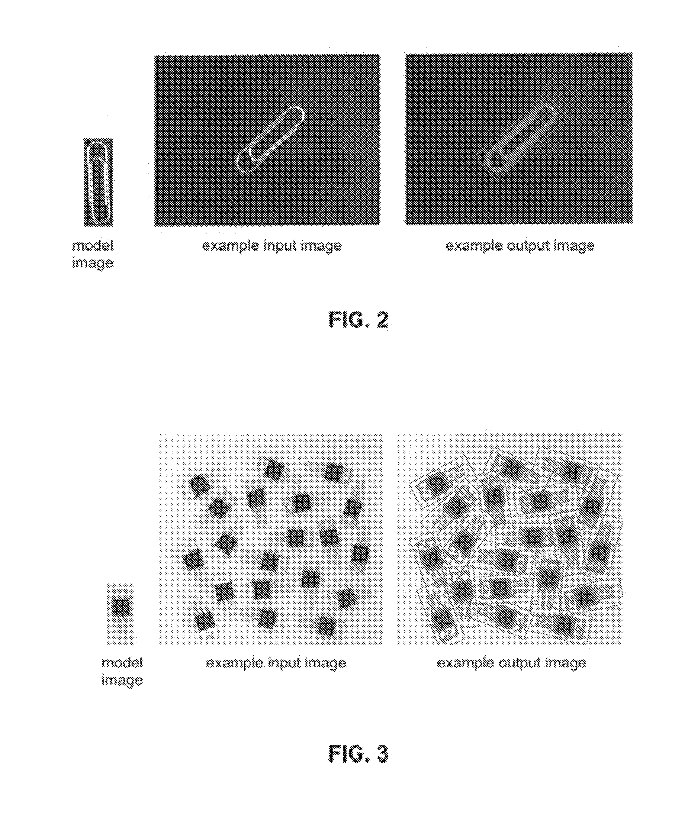
[0044]Referring to FIG. 2, in many cases a model image has a limited set of feature points but tends to have relatively sharp edge features. One such example is a paperclip. Then using a suitable matching technique it is desirable to find a matching object in one or more input images, in a computationally efficient manner. The matching object may be at an unknown position and at an unknown rotation.

[0045]Referring to FIG. 3, in many cases the input image may have one or more matching objects of interest, which may be overlapping with one another. Then using a suitable matching technique it is desirable to find matching objects in one or more input images, in a computationally efficient manner. The matching objects may be at an unknown position and at an unknown rotation.

[0046]Referring to FIG. 4, in many cases the input image may have one or more matching objects of interest, which may be overlapping with one another. Then using a suitable matching technique it is desirable to find ...


PUM


Abstract

A technique for image processing that includes receiving a model image, an input image, and registering the input image with the model image. A modified input image is determined that includes a first component that is substantially free of error components with respect to the model image and a second component that is substantially free of non-error aspects with respect to the model image. The technique determines an improved alignment of the modified input image with the model image where the improved alignment and the first and second components are determined jointly.

Description

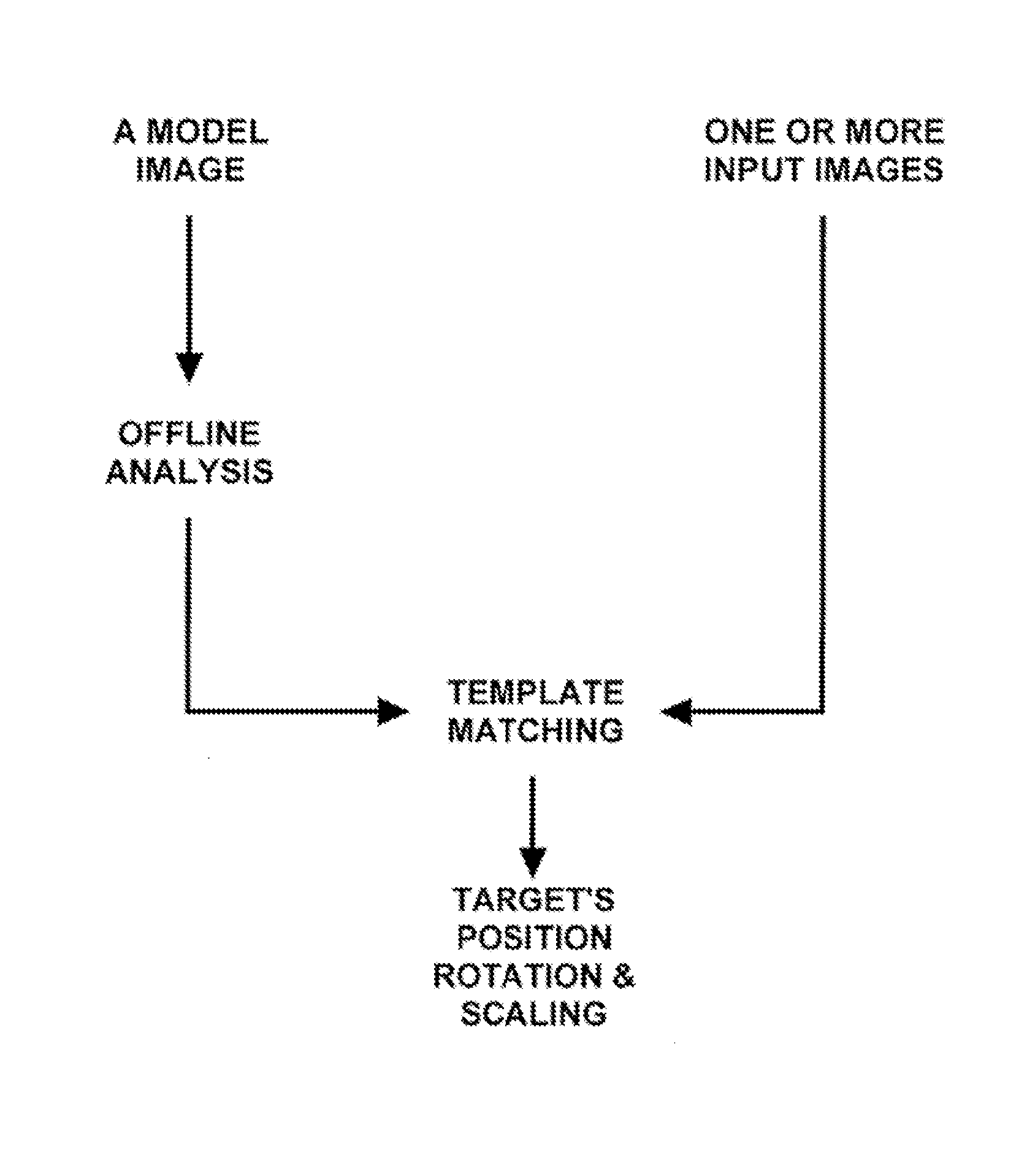
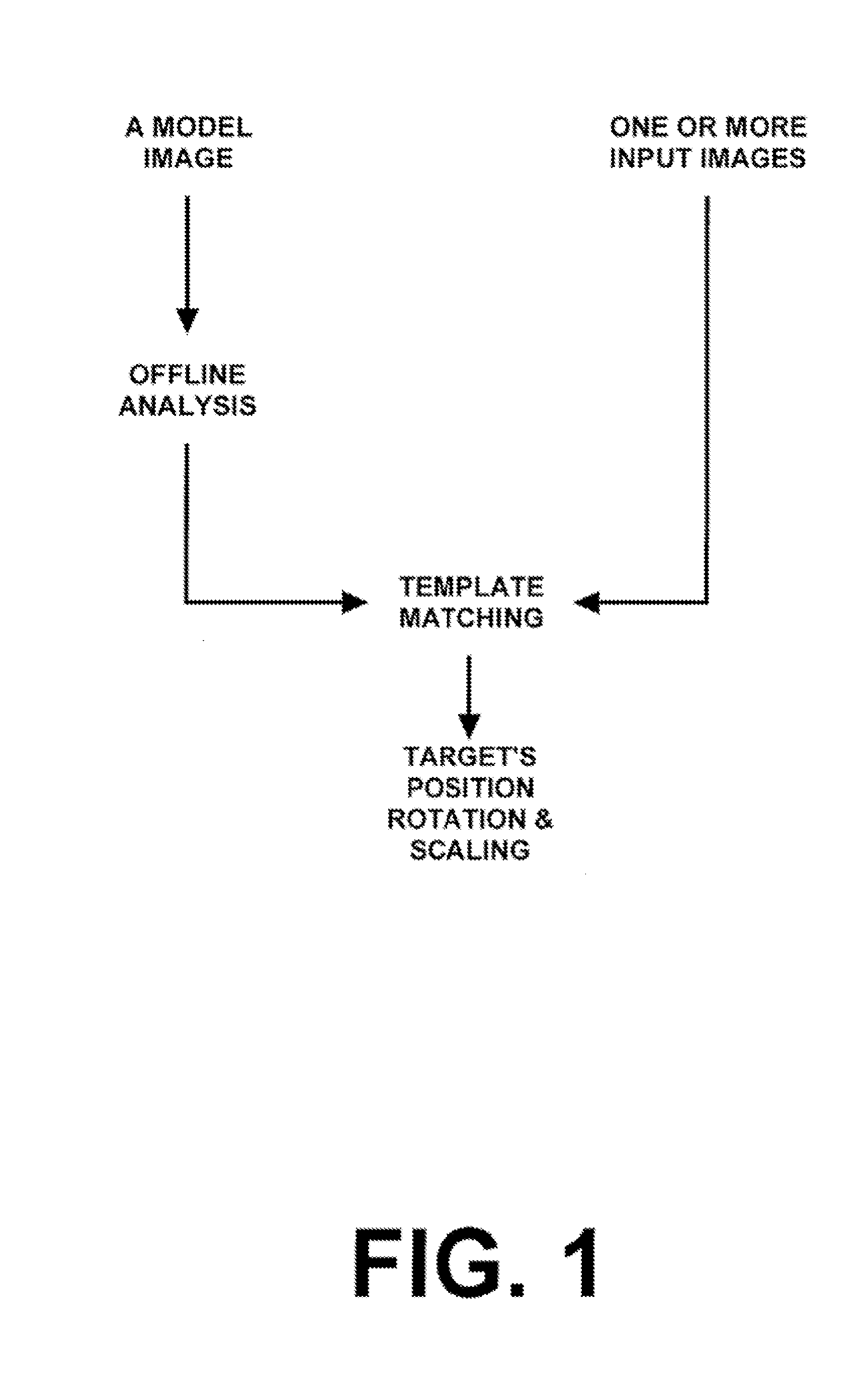
CROSS-REFERENCE TO RELATED APPLICATIONS[0001]None.BACKGROUND OF THE INVENTION[0002]The present invention relates generally to a hierarchical classification system and / or a defect detection system for an image.[0003]Referring to FIG. 1, template matching is a commonly used technique in order to perform alignment between multiple images or to recognize content in an image for classification. The template matching technique includes a given target object in a model image, and automatically finding the position, orientation, and scaling of the target object in input images. Generally, the input images undergo geometric transforms (translation, rotation, zoom, etc) and photometric changes (brightness / contrast changes, blur, noise, etc). In the context of template matching and defect detection, the relevant characteristics of the target object in the model image may be assumed to be known before the template matching to the target image is performed. The target object in the model image i...

Claims


Application Information

Patent Timeline
IPC IPC(8): G06K9/46G06V10/764
CPCG06K9/46G06T7/001G06T2207/20036G06T2207/20081G06T2207/30121G06T7/344G06V10/764G06F18/24323
Inventor XU, XINYUCHEN, XUVAN BEEK, PETRUS J.L.
Owner SHARP LAB OF AMERICA INC
Learn More