Developing Apparatus and Image Forming Apparatus

a technology of developing apparatus and image forming apparatus, which is applied in the direction of electrographic process apparatus, instruments, optics, etc., can solve the problems of smudging (scumming) of printing paper and deterioration of toner, and achieve the effect of preventing smudging of printing paper

Active Publication Date: 2014-09-18
NINGBO DELI KEBEI TECH CO LTD
View PDF10 Cites 1 Cited by
  • Summary
  • Abstract
  • Description
  • Claims
  • Application Information

AI Technical Summary

Benefits of technology

[0007]The present invention has been proposed in order to solve the aforementioned problem, and an object of the present invention is to provide a developing apparatus capable of preventing a printing paper from smudging resulting from adhesion of toner to a region of the printing paper irrelevant to an electrostatic latent image and an image forming apparatus including the developing apparatus.

Problems solved by technology

In general, toner is positively or negatively charged in a normal state, while the quantity of charge of the toner is reduced following the lapse of time or due to adhesion to the developing roller, leading to deterioration of the toner.
Consequently, the old toner adheres to a region of a printing paper irrelevant to the electrostatic latent image, to disadvantageously cause smudging (scumming) on the printing paper.

Method used


Image

  • Developing Apparatus and Image Forming Apparatus
  • Developing Apparatus and Image Forming Apparatus
  • Developing Apparatus and Image Forming Apparatus

Examples


first embodiment

Modification of First Embodiment

[0080]A developing apparatus 205 according to a modification of the first embodiment of the present invention is now described with reference to FIG. 6. According to the modification of the first embodiment of the present invention, a mesh member 255g is inclinedly arranged, dissimilarly to the aforementioned first embodiment.

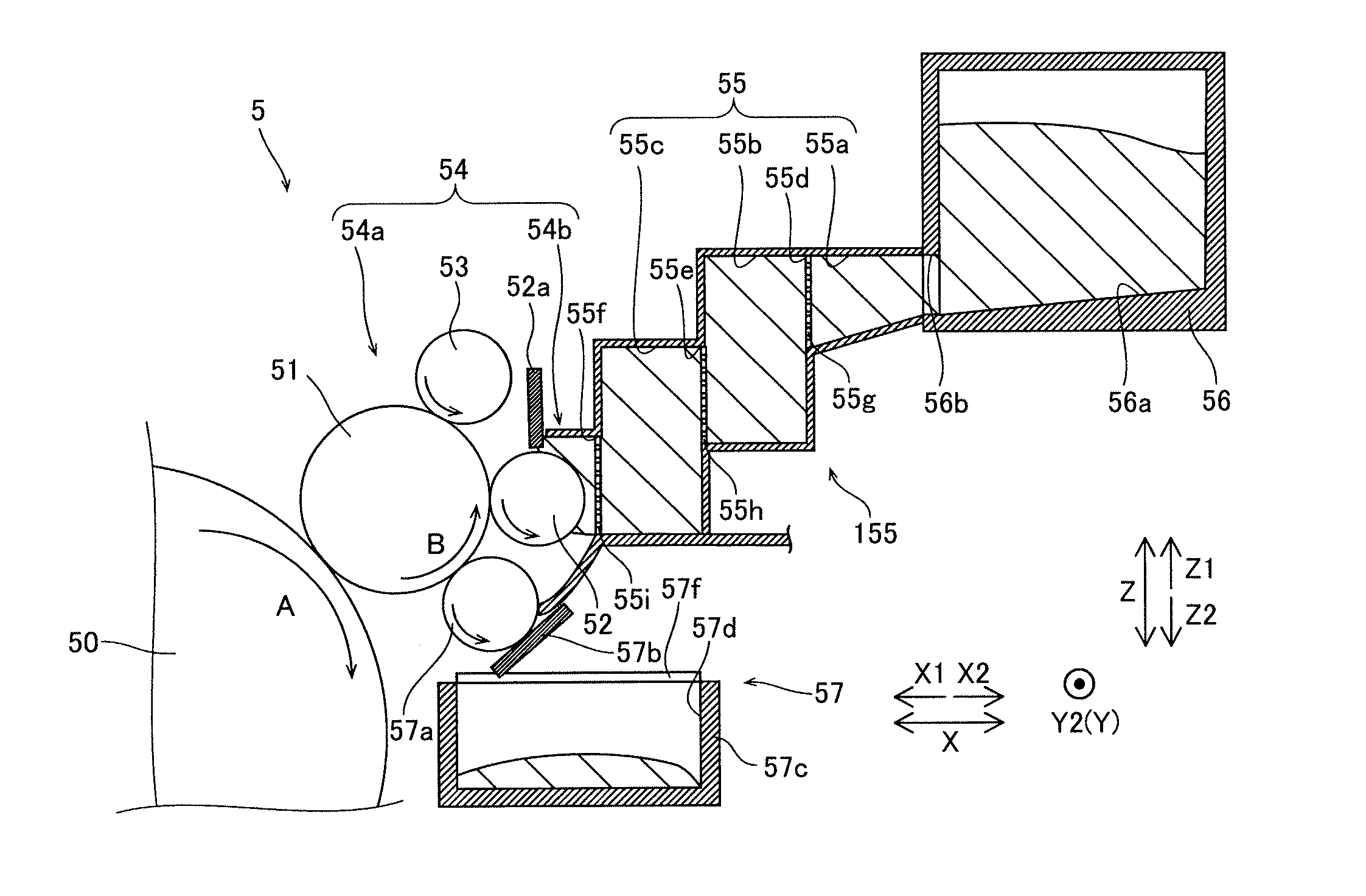
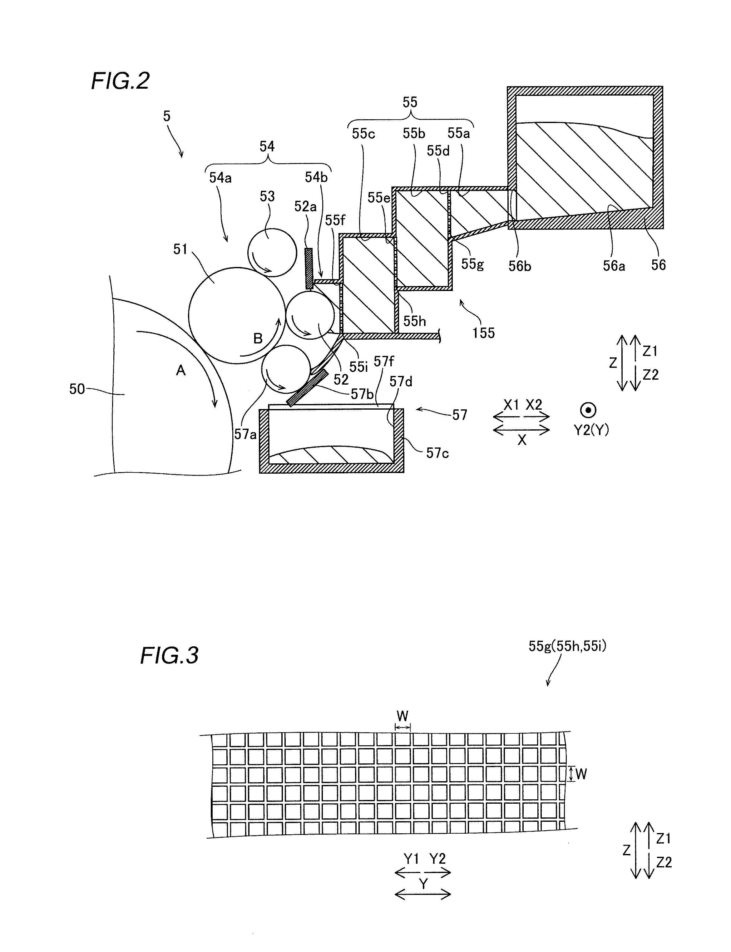
[0081]According to the modification of the first embodiment, the mesh member 255g is arranged substantially at the center of a toner supply passage 255 of the developing apparatus 205 in a direction X in an inclined state (state arranged to intersect with a direction Z) as shown in FIG. 6, dissimilarly to the aforementioned first embodiment (see FIG. 2) in which the mesh members 55g, 55h and 55i are arranged to extend along the height direction (direction Z) respectively. More specifically, the mesh member 255g is arranged in a state so inclined that that the upper end (along arrow Z1) thereof is closer to a toner carrying region...

second embodiment

[0085]A developing apparatus 305 according to a second embodiment of the present invention is now described with reference to FIGS. 7 to 11. According to the second embodiment, a toner supply passage 355 is deformable, dissimilarly to the aforementioned first embodiment.

[0086]According to the second embodiment, the toner supply passage 355 supplying toner to a toner carrying region 54 and a toner cartridge 356 storing new toner are integrally provided on the developing apparatus 305, and configured to be detachable therefrom, as shown in FIG. 7.

[0087]In the toner supply passage 355, a first chamber 355a, a second chamber 355b and a third chamber 355c are arranged in this order from a side closer to the toner cartridge 356 (along arrow X2) toward the side of the toner carrying region 54 (along arrow X1). The first chamber 355a is connected with the toner cartridge 356 along arrow X2. The second chamber 355b is connected with the first chamber 355a along arrow X2. The third chamber 35...

first modification

of Second Embodiment

[0106]A developing apparatus 405 according to a first modification of the second embodiment of the present invention is now described with reference to FIG. 12. In the developing apparatus 405 according to the first modification of the second embodiment, a toner supply passage 455 is formed to be gradually narrowing from a side closer to a toner cartridge 356 toward a side closer to a toner carrying region 54, dissimilarly to the aforementioned second embodiment.

[0107]According to the first modification of the second embodiment, the toner supply passage 455 of the developing apparatus 405 is not configured to be deformable dissimilarly to the toner supply passage 355 (see FIG. 7) according to the aforementioned second embodiment, as shown in FIG. 12. Further, the toner supply passage 455 is provided with an inclined structure 455a. The inclined structure 455a is so configured that an upper surface 455b is inclined downward (along arrow Z2) from the side closer to...


PUM


Abstract

This developing apparatus includes a toner supply passage for supplying new toner fed from a toner cartridge to a toner carrying region where a toner carrier is arranged, and the toner supply passage is provided with a backflow prevention portion for preventing old toner from backflowing toward the toner cartridge.

Description

BACKGROUND OF THE INVENTION[0001]1. Field of the Invention[0002]The present invention relates to a developing apparatus and an image forming apparatus, and more particularly, it relates to a developing apparatus and an image forming apparatus each including a toner carrier for supplying toner to an electrostatic latent image formed on an image carrier.[0003]2. Description of the Background Art[0004]An image forming apparatus including a developing apparatus including a toner carrier for supplying toner to an electrostatic latent image formed on an image carrier is known in general, as disclosed in Japanese Patent Laying-Open No. 2008-107442, for example.[0005]The aforementioned Japanese Patent Laying-Open No. 2008-107442 discloses an image forming apparatus including a developing apparatus including a photosensitive belt forming an electrostatic latent image, a developing unit including a developing roller for supplying toner to the electrostatic latent image formed on the photosens...

Claims


Application Information

Patent Timeline
Patent Type & Authority Applications(United States)
IPC IPC(8): G03G15/08
CPCG03G15/0865G03G15/0886G03G15/0874G03G15/0875G03G15/0877G03G15/0879
Inventor ASAI, TOSHINORI
Owner NINGBO DELI KEBEI TECH CO LTD
Why Eureka
Try Eureka