Powder container and image forming apparatus

a technology of image forming apparatus and powder container, which is applied in the field of powder container, can solve the problems of scattering of powder scattering of toner, and powder leaked along with the removal of the conveying nozzle, and achieve the effect of preventing the scattering of powder

Active Publication Date: 2014-09-18
RICOH KK
View PDF2 Cites 84 Cited by
  • Summary
  • Abstract
  • Description
  • Claims
  • Application Information

AI Technical Summary

Benefits of technology

[0012]According to the invention, it is possible to prevent scattering of leaked powder when a conveying nozzle is removed from a powder container.

Problems solved by technology

Therefore, when the conveying nozzle is removed from the toner container, some of the toner in contact with the conveying nozzle may remain attached to the conveying nozzle and may pass through the nozzle receiving opening along with the conveying nozzle, so that the toner may be leaked from the nozzle receiving opening resulting in toner scattering.
However, in any powder that contains powder other than toner, if the container is configured to convey and discharge the powder from the inside to the outside by inserting a conveying nozzle fixed to a powder conveying device, powder leaked along with removal of the conveying nozzle may be scattered.

Method used


Image

  • Powder container and image forming apparatus
  • Powder container and image forming apparatus
  • Powder container and image forming apparatus

Examples


first embodiment

[0097]Exemplary embodiments of a copier (hereinafter, described as a copier 500) as an image forming apparatus according to the present invention will be explained below.

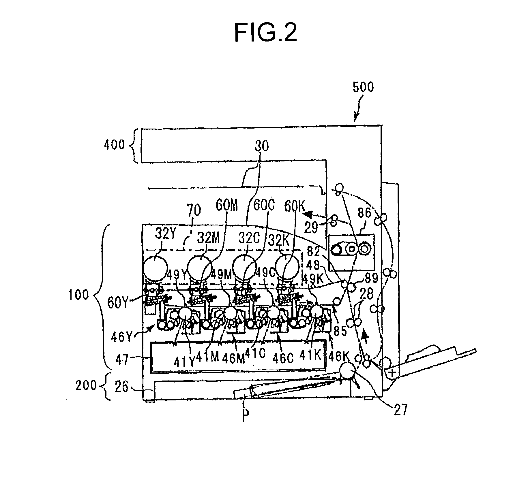
[0098]FIG. 2 is an overall configuration diagram of the copier 500 common to first to twentieth embodiments. The copier 500 includes a copier body (hereinafter, described as a printer 100), a sheet feed table (hereinafter, described as a sheet feeder 200), and a scanner (hereinafter, described as a scanner 400) mounted on the printer 100.

[0099]Toner containers 32 (Y, M, C, K) serving as four powder containers corresponding to respective colors (yellow, magenta, cyan, black) are detachably (replaceably) attached to a container holding section 70 provided in the upper part of the printer 100. An intermediate transfer unit 85 is arranged below the container holding section 70.

[0100]The intermediate transfer unit 85 includes an intermediate transfer belt 48, four primary-transfer bias rollers 49 (Y, M, C, K), a secondar...

second embodiment

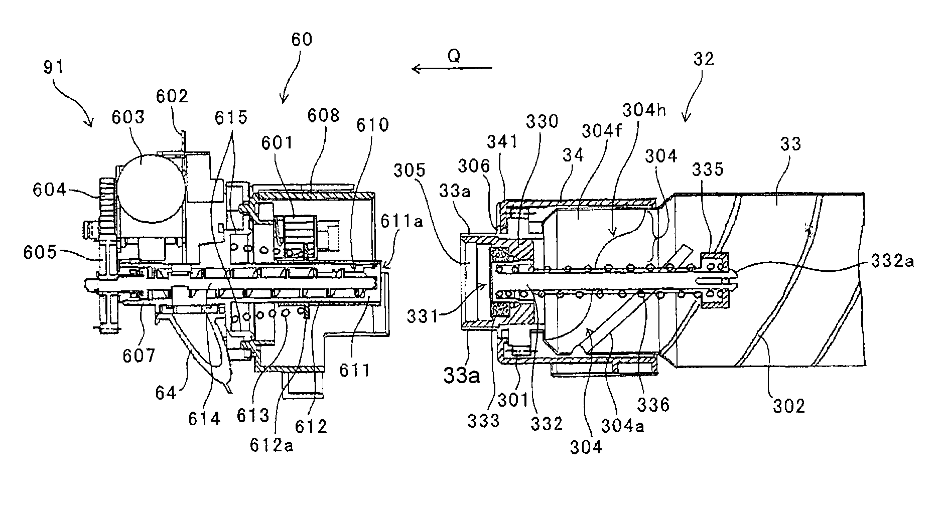
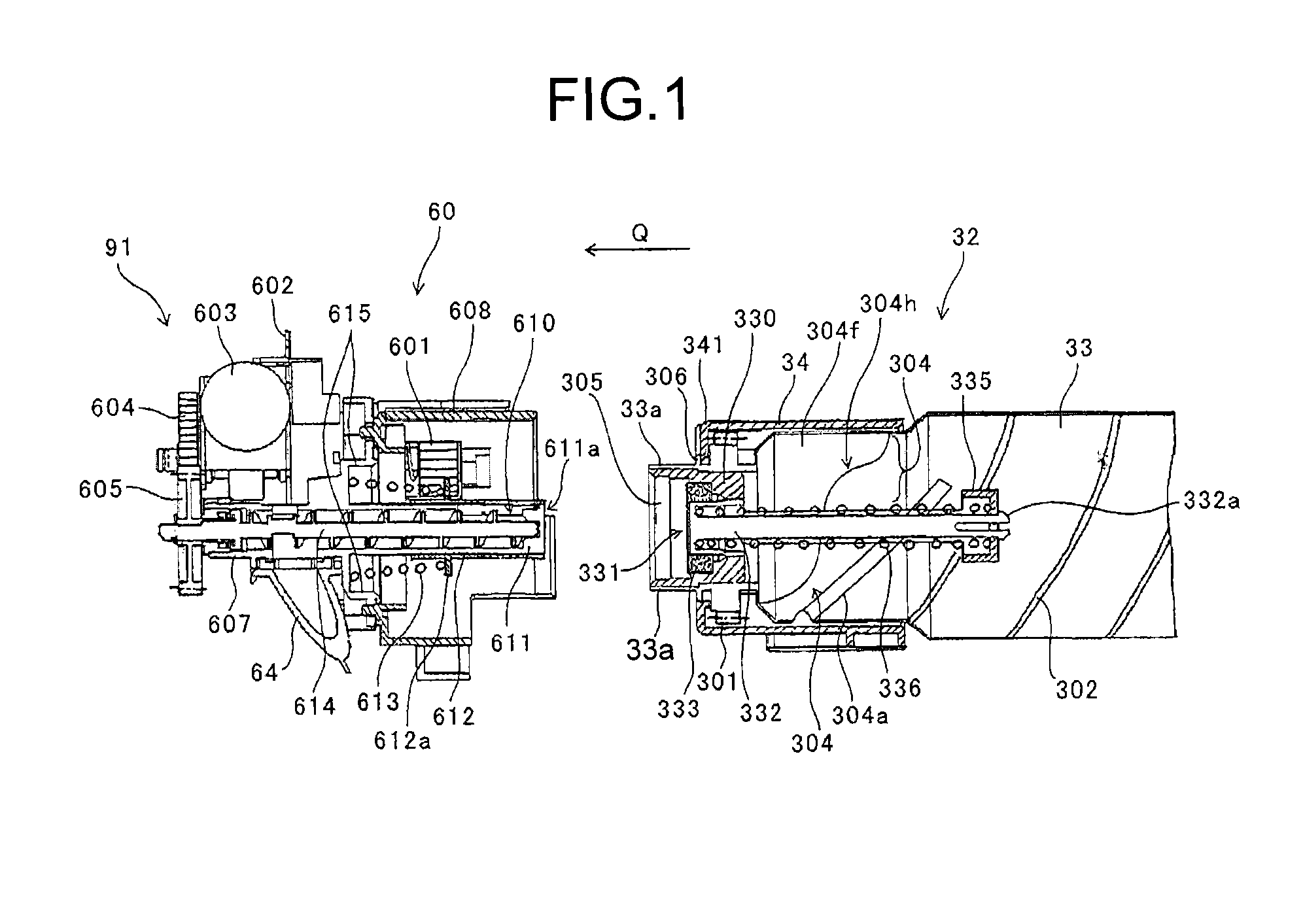
[0187]A toner container 32 according to a second embodiment will be explained below, in which the container shutter 332 is modified compared with the toner container 32 of the first embodiment.

[0188]The toner container 32 can be detached from the copier 500 in the state illustrated in FIG. 6. However, when the toner container 32 alone is transported or is set to the main body by a user, the toner container 32 may be dropped.

[0189]FIG. 19 is an explanatory diagram illustrating a state where the toner container 32 falls with the rear end facing downward. An arrow δ1 in FIG. 19 indicates the falling direction.

[0190]If the toner container 32 falls down and hit the floor as illustrated in FIG. 19, the inertia force of the container shutter 332 acts in the same direction as the falling direction as indicated by an arrow δ2 in FIG. 19. The inertia force increases as the impact due to falling increases, and if the inertial force becomes greater than the pressing force of the container shutt...

third embodiment

[0239]A modification of rotation timings of the toner container 32 etc. according to a third embodiment will be explained.

[0240]In the configurations explained above in the first and the second embodiments, the toner container 32 and the conveying screw 614 are rotated simultaneously. However, regarding the rotation timings, it may be possible to rotate only the toner container 32 at the start of toner replenishment, and subsequently rotate the conveying screw 614 after a lapse of a predetermined time. Furthermore, it may be possible to stop the toner container 32 at the end of the toner replenishment, and subsequently stop the conveying screw 614 after a lapse of a predetermined time. A timing chart of the above rotation timings is illustrated in FIG. 29.

[0241]In the configuration with the rotation timings illustrated in FIG. 29, when the toner replenishment is stopped, rotation of the toner container 32 is stopped before rotation of the conveying screw 614 inside the conveying noz...


PUM


Abstract

A powder conveying device includes: a conveying nozzle, provided with a powder receiving opening; an open/close member to open/close the powder receiving opening; a flange provided to the open/close member; a biasing member to bias the open/close member; and a container setting section to which a part of a powder container is to be fit. The powder container includes: a conveyor to convey the powder from a second end of the powder container to a first end; a container opening protruding from the first end; a nozzle receiving opening into which the conveying nozzle is to be inserted; and a butting portion provided in the container opening, to butt against the flange. When the powder container is attached to the powder conveying device, the container opening is fitted to the container setting section, and the flange and the biasing member are housed in an inner space of the container opening.

Description

CROSS-REFERENCE TO RELATED APPLICATIONS[0001]This application is a continuation of PCT international application Ser. No. PCT / JP2012 / 081219 filed on Nov. 26, 2012 which designates the United States, incorporated herein by reference, and which claims the benefit of priority from Japanese Patent Applications No. 2011-258355, filed on Nov. 25, 2011, No. 2011-258356, filed on Nov. 25, 2011, No. 2011-258358, filed on Nov. 25, 2011, No. 2012-137077, filed on Jun. 18, 2012, No. 2012-248855, filed on Nov. 12, 2012, and No. 2012-256921, filed on Nov. 22, 2012, incorporated herein by reference.BACKGROUND OF THE INVENTION[0002]1. Field of the Invention[0003]The present invention relates to a powder container for containing powder, such as toner, and an image forming apparatus that conveys the powder from the powder container to a conveying destination.[0004]2. Description of the Related Art[0005]In image forming apparatuses, such as copiers, printers, or facsimile machines, using an electropho...

Claims


Application Information

Patent Timeline
Patent Type & Authority Applications(United States)
IPC IPC(8): G03G15/08
CPCG03G15/0865G03G15/0886G03G15/0872G03G15/0863G03G15/0877G03G2215/0668G03G2215/0697G03G15/08
Inventor HOSOKAWA, HIROSHIKATO, SHUNJITAMAKI, SHINJIIKEGUCHI, HIROSHITERAZAWA, SEIJIYAMABE, JUNJIMITSUISHI, KAORITOMOTAKA, TOSHIHIDEWATANABE, TSUNEHIROKIKUCHI, KENJI
Owner RICOH KK
Why Eureka
Try Eureka