
Removable vena cava filter having primary and secondary struts

Active Publication Date: 2014-09-18
COOK MEDICAL TECH LLC
View PDF2 Cites 1 Cited by
  • Summary
  • Abstract
  • Description
  • Claims
  • Application Information

AI Technical Summary

Benefits of technology

[0006]One embodiment of the present invention generally provides a removable

Problems solved by technology

During such medical conditions, the need for filtering devices arises due to the likelihood of thrombosis in the peripheral vasculature of patients wherein thrombi break away from the vessel wall, risking downstream embolism or embolization.
For example, depending on the size, such thrombi pose a serious risk of pulmonary embolism wherein blood clots migrate from the peripheral v

Method used


Image

  • Removable vena cava filter having primary and secondary struts
  • Removable vena cava filter having primary and secondary struts
  • Removable vena cava filter having primary and secondary struts

Examples


Example

DETAILED DESCRIPTION OF THE DRAWINGS

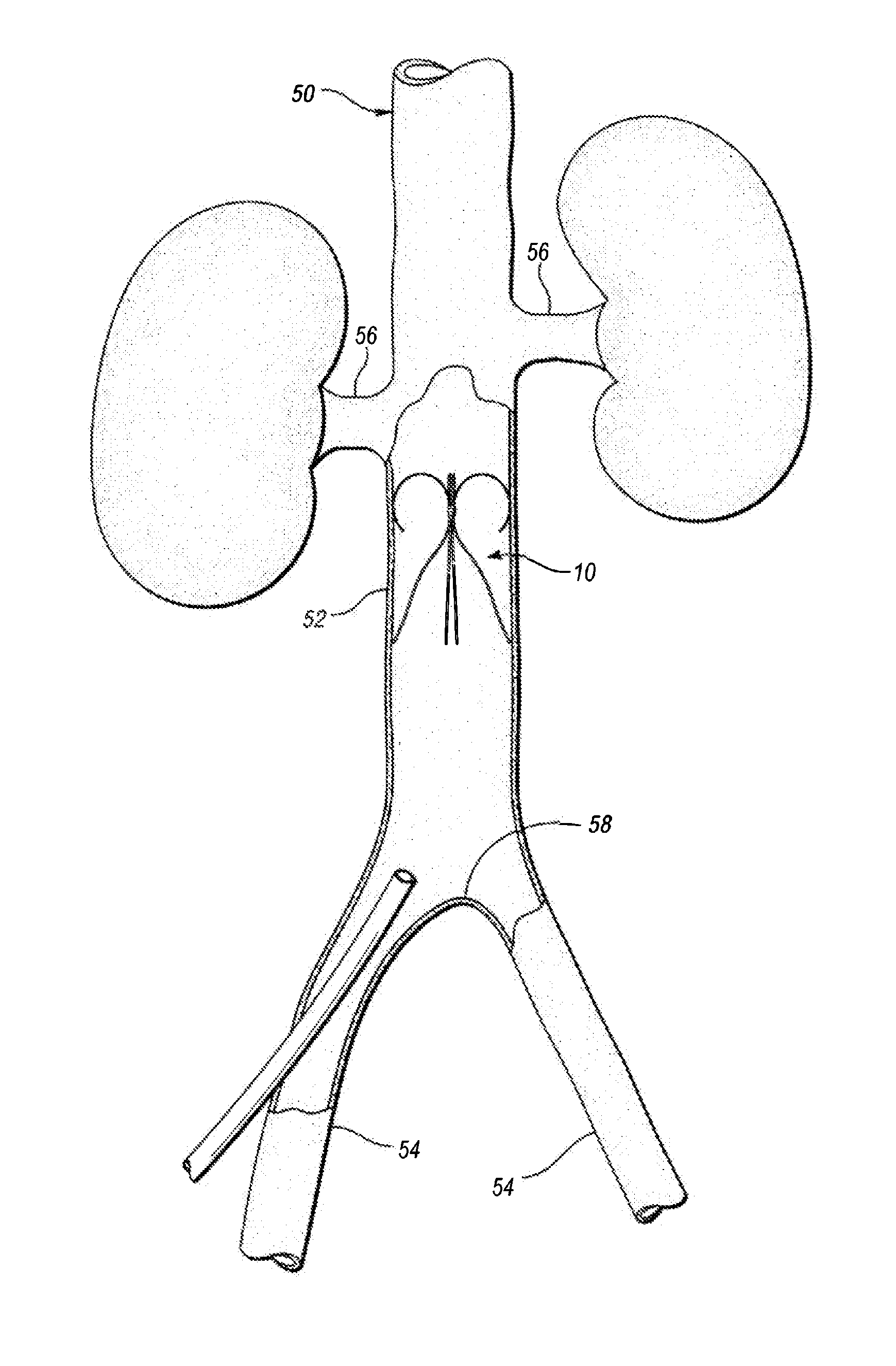
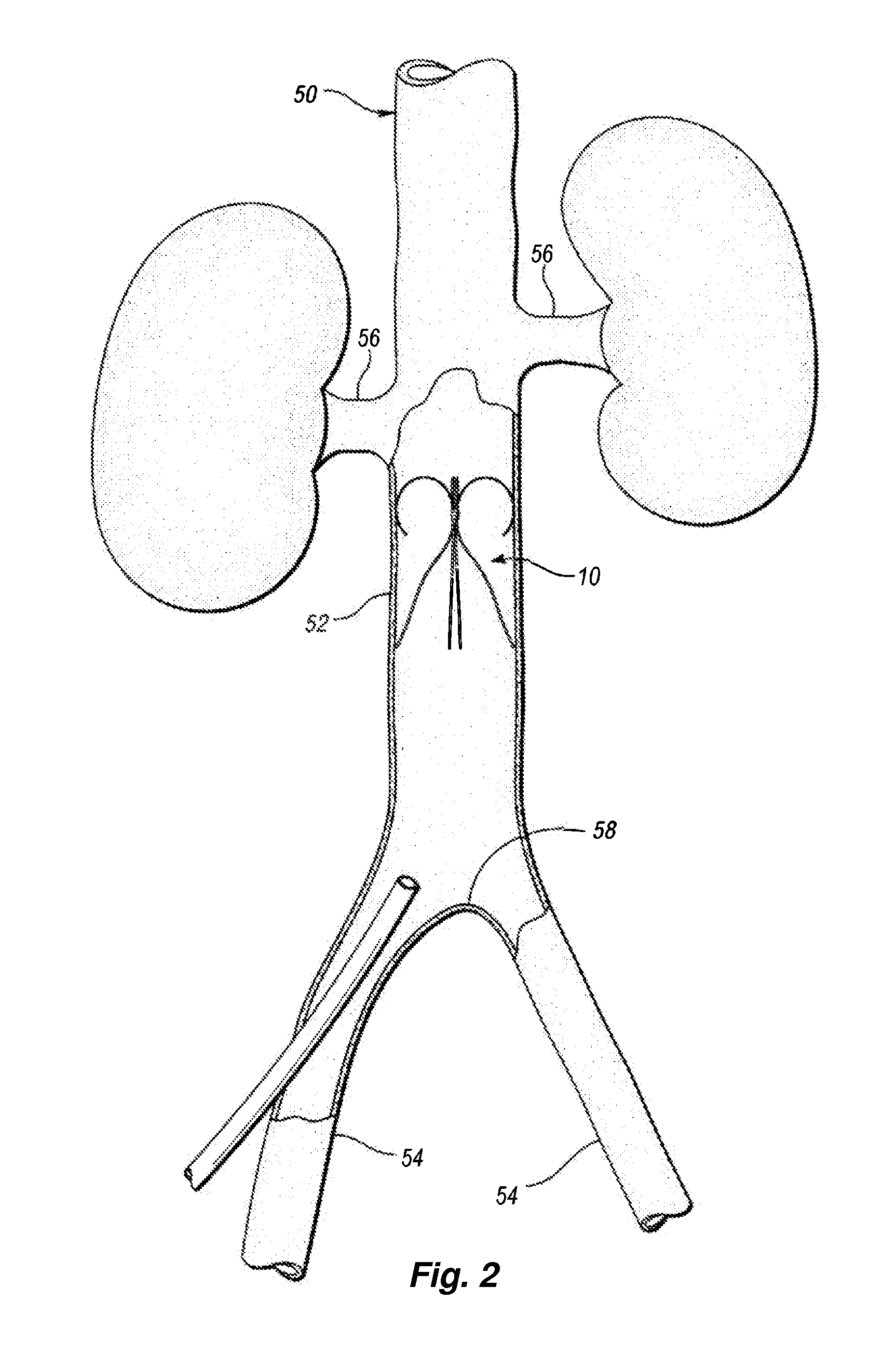
[0020]In accordance with one embodiment of the present invention, FIG. 2 illustrates a vena cava filter 10 implanted in the vena cava 50 for the purpose of lysing or capturing thrombi carried by the blood flowing through the iliac veins 54 toward the heart and into the pulmonary arteries. As shown, the iliac veins merge at juncture 58 into the vena cava 50. The renal veins 56 from the kidneys 62 join the vena cava 50 downstream of juncture 58. The portion of the vena cava 50, between the juncture 58 and the renal veins 56, defines the inferior vena cava 52 in which the vena cava filter 10 has been percutaneously deployed through one of the femoral veins. Preferably, the vena cava filter 10 has a length smaller than the length of the inferior vena cava 52. If the lower part of the filter extends into the iliac veins, filtering effectiveness will be compromised and if the filter wires cross over the origin of the renal veins the filter wires might i...


PUM


Abstract

A removable filter has a hub defining a waist and a longitudinal filter axis; a plurality of primary struts extending from a first axial side of the hub, and a plurality of secondary struts extending from a second axial side of the hub opposite the first axial side. The secondary struts form a radially outward arc extending from the hub over an angle of at least about 180° in the expanded state, preferably between about 190° and about 270°. A retrieval coil with a proximal end fastened to an elongated wire has several longitudinally offset windings. The retrieval coil is preferably more rigid than the primary struts. The coil may preferably have a distal winding with an inner diameter that is greater than the diameter of the hub and smaller than the diameter of the filter in the expanded state.

Description

FIELD OF THE INVENTION[0001]The present invention relates to medical devices. More particularly, the invention relates to a removable vena cava clot filter that can be percutaneously placed in and removed from the vena cava of a patient.BACKGROUND OF THE INVENTION[0002]Filtering devices that are percutaneously placed in the vena cava have been available for over thirty years. A need for filtering devices arises in trauma patients, orthopedic surgery patients, neurosurgery patients, or in patients having medical conditions requiring bed rest or non-movement. During such medical conditions, the need for filtering devices arises due to the likelihood of thrombosis in the peripheral vasculature of patients wherein thrombi break away from the vessel wall, risking downstream embolism or embolization. For example, depending on the size, such thrombi pose a serious risk of pulmonary embolism wherein blood clots migrate from the peripheral vasculature through the heart and into the lungs.[00...

Claims


Application Information

Patent Timeline
IPC IPC(8): A61F2/01
CPCA61F2/01A61F2002/016A61F2230/0058A61F2230/0093A61F2/0103A61F2/0105A61F2/011A61F2/012
Inventor JOHNSEN, JEPPE BØCKHAUS
Owner COOK MEDICAL TECH LLC
Features
  • Generate Ideas
  • Intellectual Property
  • Life Sciences
  • Materials
  • Tech Scout
  • Unparalleled Data Quality
  • Higher Quality Content
  • 60% Fewer Hallucinations
Learn More