

Robot system and method for controlling robot system
a robot and robot technology, applied in the direction of electric programme control, program control, instruments, etc., can solve the problems of robot and person interference with each other
- Summary
- Abstract
- Description
- Claims
- Application Information
AI Technical Summary
Benefits of technology
Problems solved by technology
Method used
Image

Examples
first embodiment
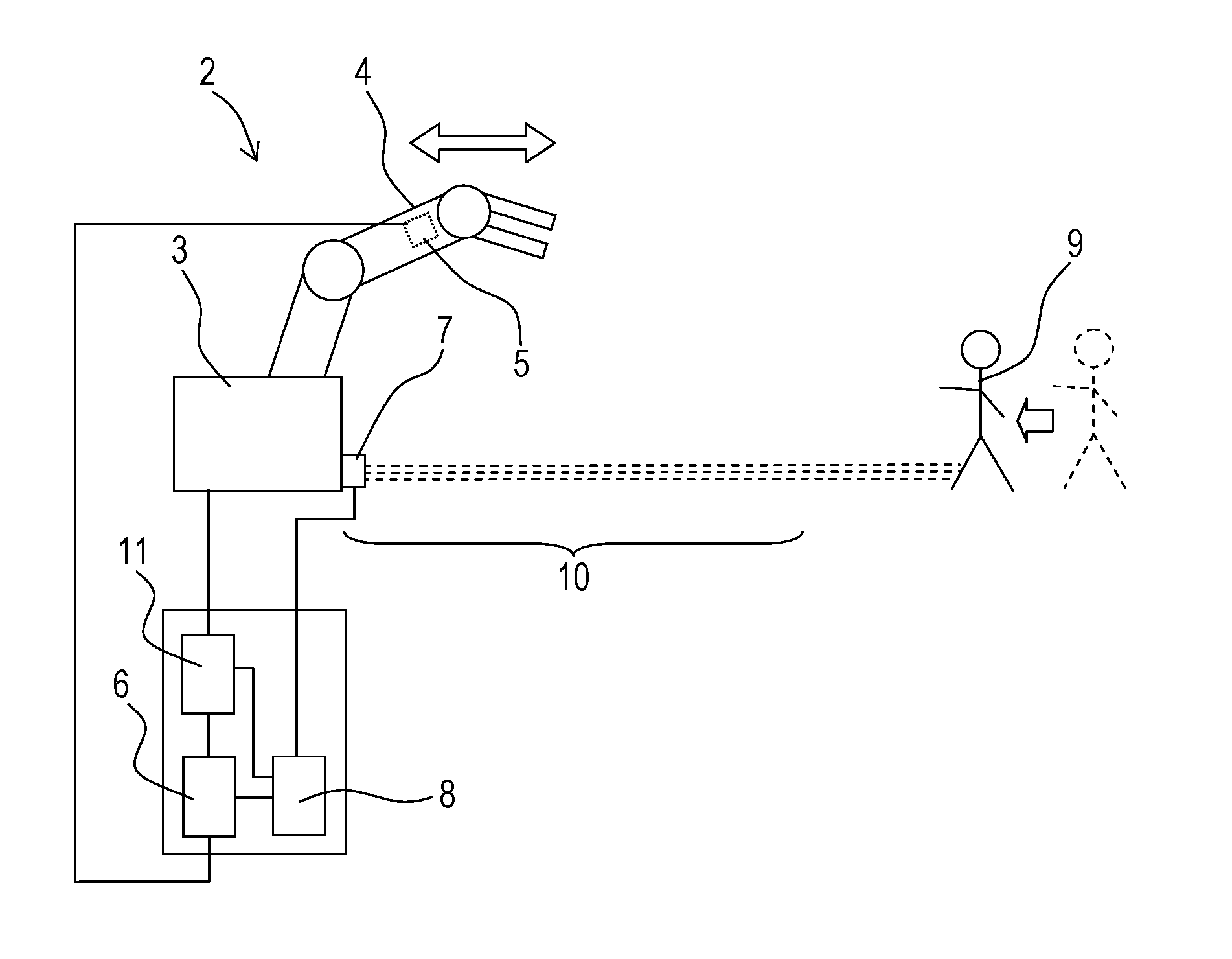
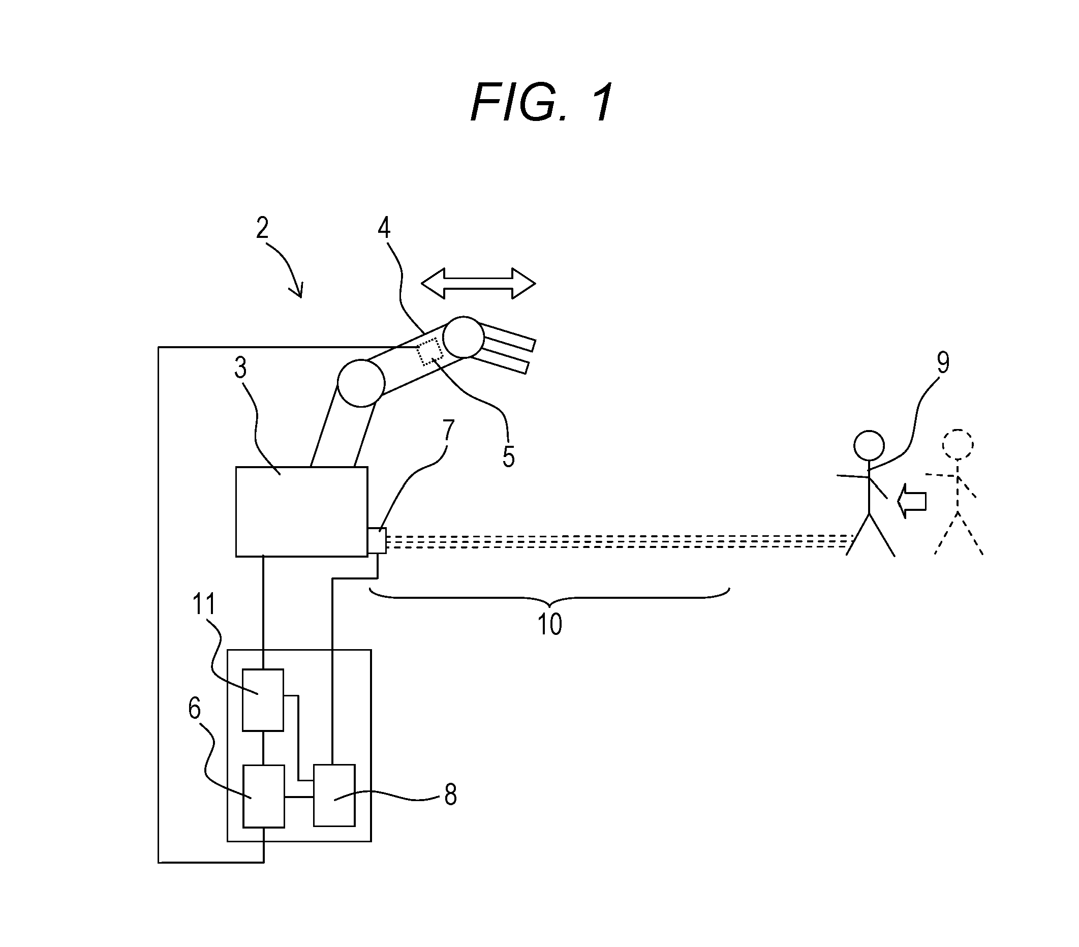
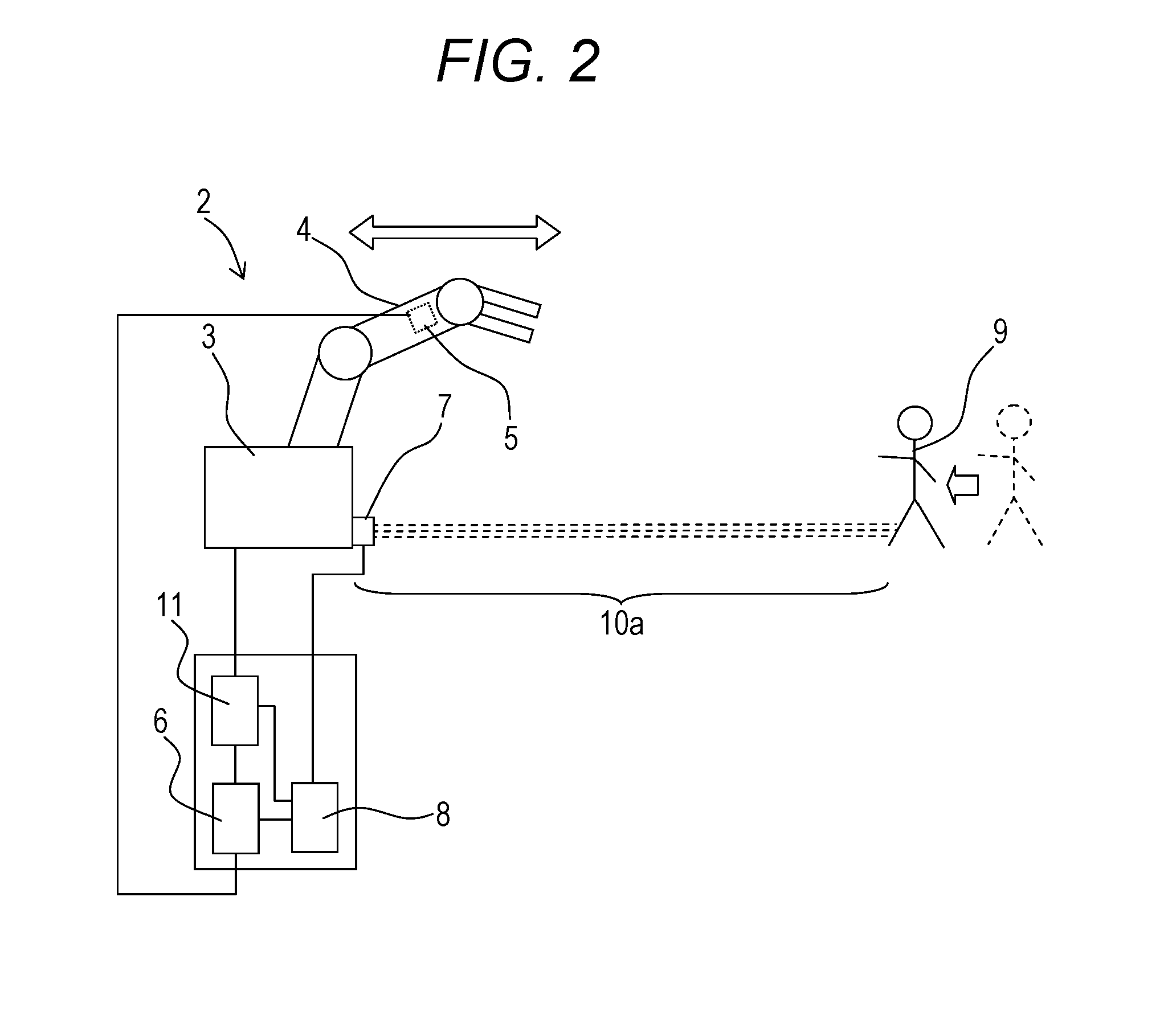
[0030]A robot system according to a first embodiment is hereinafter described with reference to drawings. FIG. 1 is a schematic diagram illustrating the operation of the robot system according to the first embodiment. FIG. 2 is a schematic diagram illustrating an example in which the motion speed of a working arm is higher than that in the state depicted in FIG. 1. FIG. 3 is a schematic diagram illustrating an example in which the motion speed of the working arm is lower than that in the state depicted in FIG. 1. In FIG. 1, FIG. 2, and FIG. 3, the magnitude of the absolute value of the motion speed of the working arm is represented by the length of the arrow depicted above a working arm 4.
[0031]The motion speed of the working arm 4 generally refers to the motion speed of an end of the working arm.
[0032]As illustrated in FIG. 1, a robot system 2 includes a robot 3, a motion speed detection unit 5, a region setting unit 6, a moving body detection unit 7, an abnormality determination u...
first modified example
[0049]FIG. 5 is a schematic diagram illustrating the operation of a robot system according to a first modified example. As illustrated in FIG. 5, a robot system 2a includes the robot 3, the motion speed detection unit 5, the region setting unit 6, a moving body detection unit 7a, the abnormality determination unit 8, and the motion control unit 11. The moving body detection unit 7a of the robot system 2a includes a plurality of moving body sensing sensors disposed on a ceiling around the robot 3. These moving body sensing sensors are disposed at predetermined intervals at different positions whose distance from the robot 3 is different. In the robot system 2a, the position of the moving body 9 other than the robot 3 can be detected using such plural moving body sensing sensors. In the example illustrated in FIG. 5, the three moving body sensing sensors are disposed at almost equal intervals on the ceiling around the robot 3. The moving body sensing sensor may be, for example, a know...
second modified example
[0050]FIG. 6 is a flowchart illustrating the procedure for changing the range of the region 10 and the procedure for the abnormality determination of the robot system 2 or 2a according to a second modified example. As illustrated in FIG. 6, in the procedure according to the second modified example, the motion speed detection unit 5 first detects the motion speed of the working arm 4 in Step S9. Next, in Step S10, the region setting unit 6 sets the region 10 around the robot 3 on the basis of the detected motion speed of the working arm 4. Then, in Step S11, the moving body detection unit 7 or 7a detects the position of the moving body 9. Next, in Step S12, the abnormality determination unit 8 determines whether the position of the moving body 9 is within the region 10 or not. If the position of the moving body 9 is within the region 10, the process advances to Step S16 where the state is determined as being abnormal. In the procedure according to the second modified example, after t...
PUM
 Abstract
Description
Claims
Application Information