Cleaning system
a cleaning system and cleaning technology, applied in the field of cleaning systems, can solve the problems of inconvenient user experience, time-consuming and labor-intensive, and irreparable damag
- Summary
- Abstract
- Description
- Claims
- Application Information
AI Technical Summary
Benefits of technology
Problems solved by technology
Method used
Image

Examples
Embodiment Construction
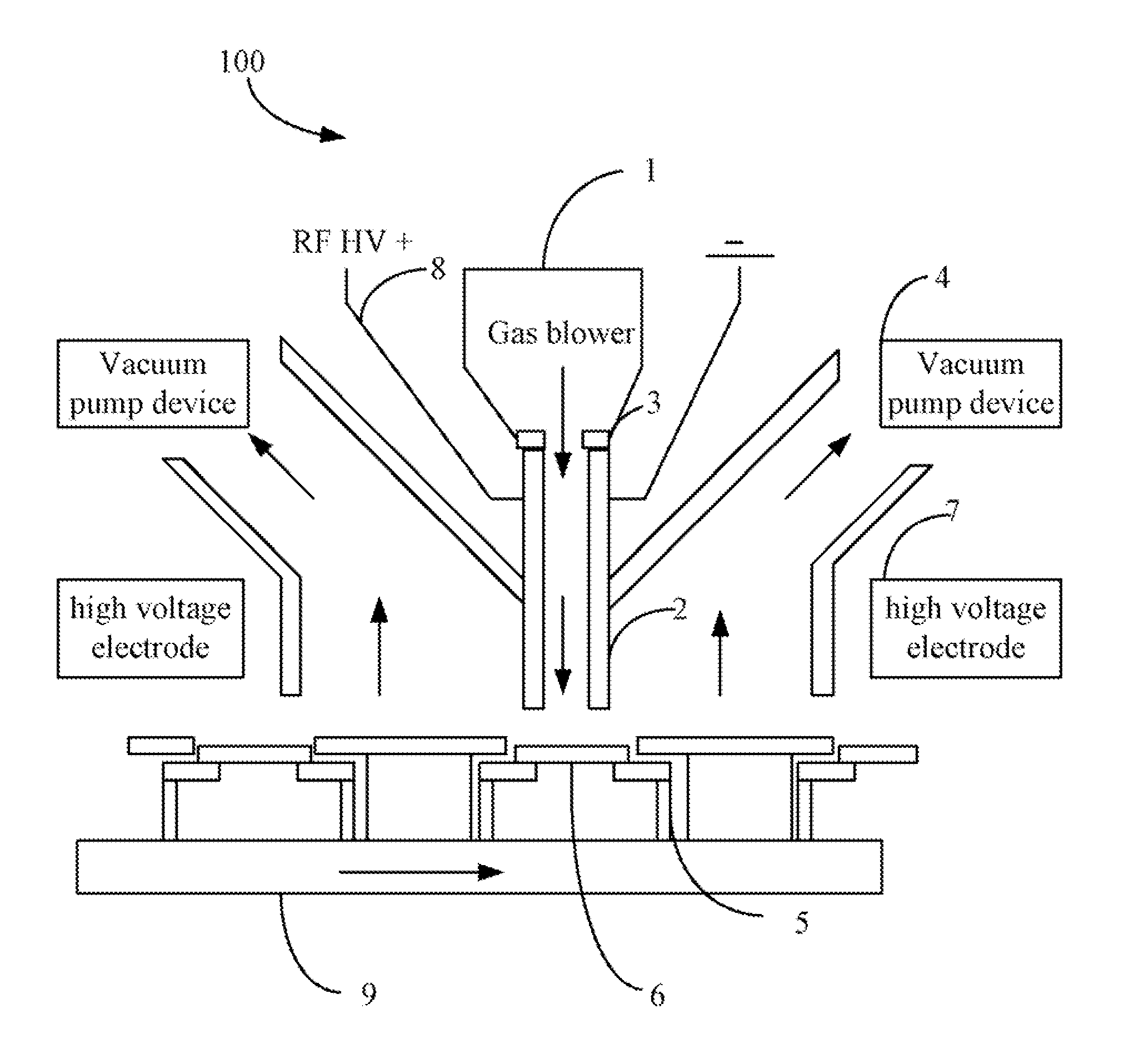
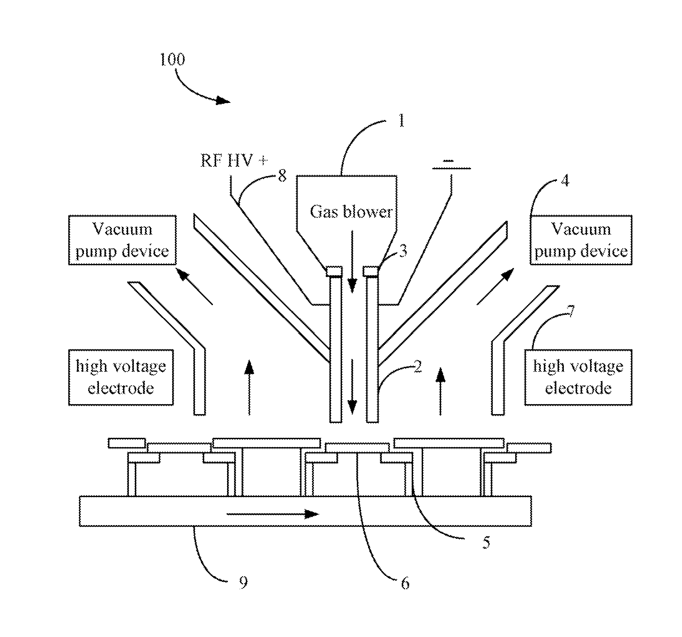
[0007]The FIGURE shows an gas cleaning system 100 of an embodiment. In the embodiment, the gas cleaning system 100 is used for removing contaminant particles on a surface of an image sensor 6. The cleaning system 100 includes a gas blower 1, two plate electrodes 2 parallel to each other, two electromagnetic valves 3 arranged between the gas blower 1 and the two plate electrodes 2, a high frequency voltage source 8, two vacuum pump devices 4 arranged adjacent to the two plate electrodes 2, and two high voltage electrodes 7 arranged adjacent to the two vacuum pump devices 4. The plate electrodes 2 cooperatively defines a gas channel for allowing the mixed gas to pass therethrough.
[0008]A transmission belt 9 is movably placed below the two plate electrodes 2. The transmission belt 9 includes a number of support portions 5. Each of the support portions 5 supports an optical sensor 6. The two plate electrodes 2 are aligned with one of the support portions 5.
[0009]The gas blower 1 blows a...
PUM
 Abstract
Description
Claims
Application Information
 - R&D Engineer
- R&D Manager
- IP Professional
- Industry Leading Data Capabilities
- Powerful AI technology
- Patent DNA Extraction
Browse by: Latest US Patents, China's latest patents, Technical Efficacy Thesaurus, Application Domain, Technology Topic.
© 2024 PatSnap. All rights reserved.Legal|Privacy policy|Modern Slavery Act Transparency Statement|Sitemap