Rotational damper

Active Publication Date: 2014-09-25
AUDI AG
View PDF5 Cites 4 Cited by
  • Summary
  • Abstract
  • Description
  • Claims
  • Application Information

AI Technical Summary

Benefits of technology

[0015]According to another advantageous feature of the invention, the housing attachment can form the friction surface of the centrifugal brake, thereby obviating the requirement for additional parts for providing the friction surface or for individual friction surfaces.
[0016]According

Problems solved by technology

This also at the same time limits the maximally provided damping force.
However, for exceptional situations (for example when the vehicle drives over a bump with high speed) the high damping force of a hydraulic damper has to be provided also with an electric damper.
Increasing the tilting moment by configuring t

Method used


Image

  • Rotational damper
  • Rotational damper
  • Rotational damper

Examples


Example

[0022]Throughout all the Figures, same or corresponding elements are generally indicated by same reference numerals. These depicted embodiments are to be understood as illustrative of the invention and not as limiting in any way. It should also be understood that the drawings are not necessarily to scale and that the embodiments are sometimes illustrated by graphic symbols, phantom lines, diagrammatic representations and fragmentary views. In certain instances, details which are not necessary for an understanding of the present invention or which render other details difficult to perceive may have been omitted.

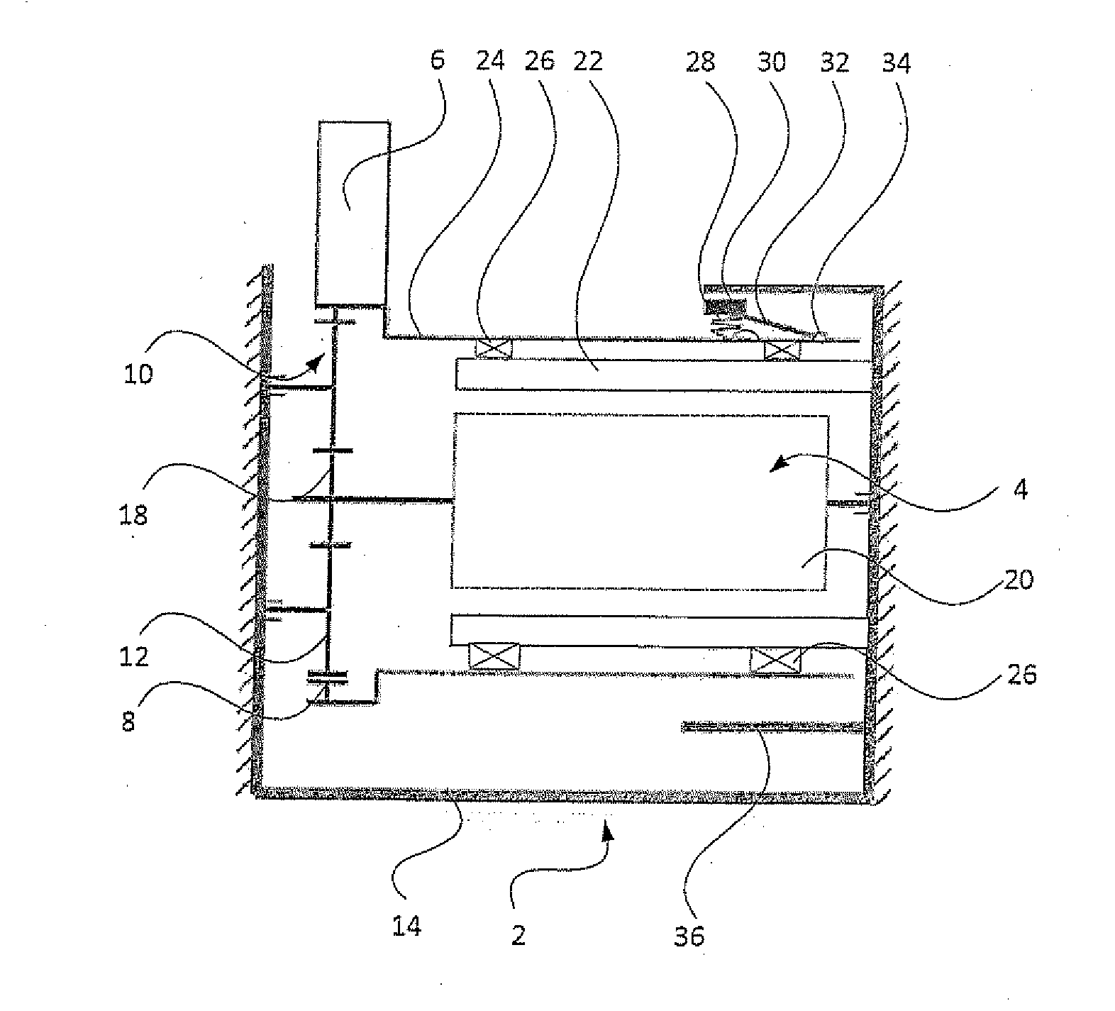
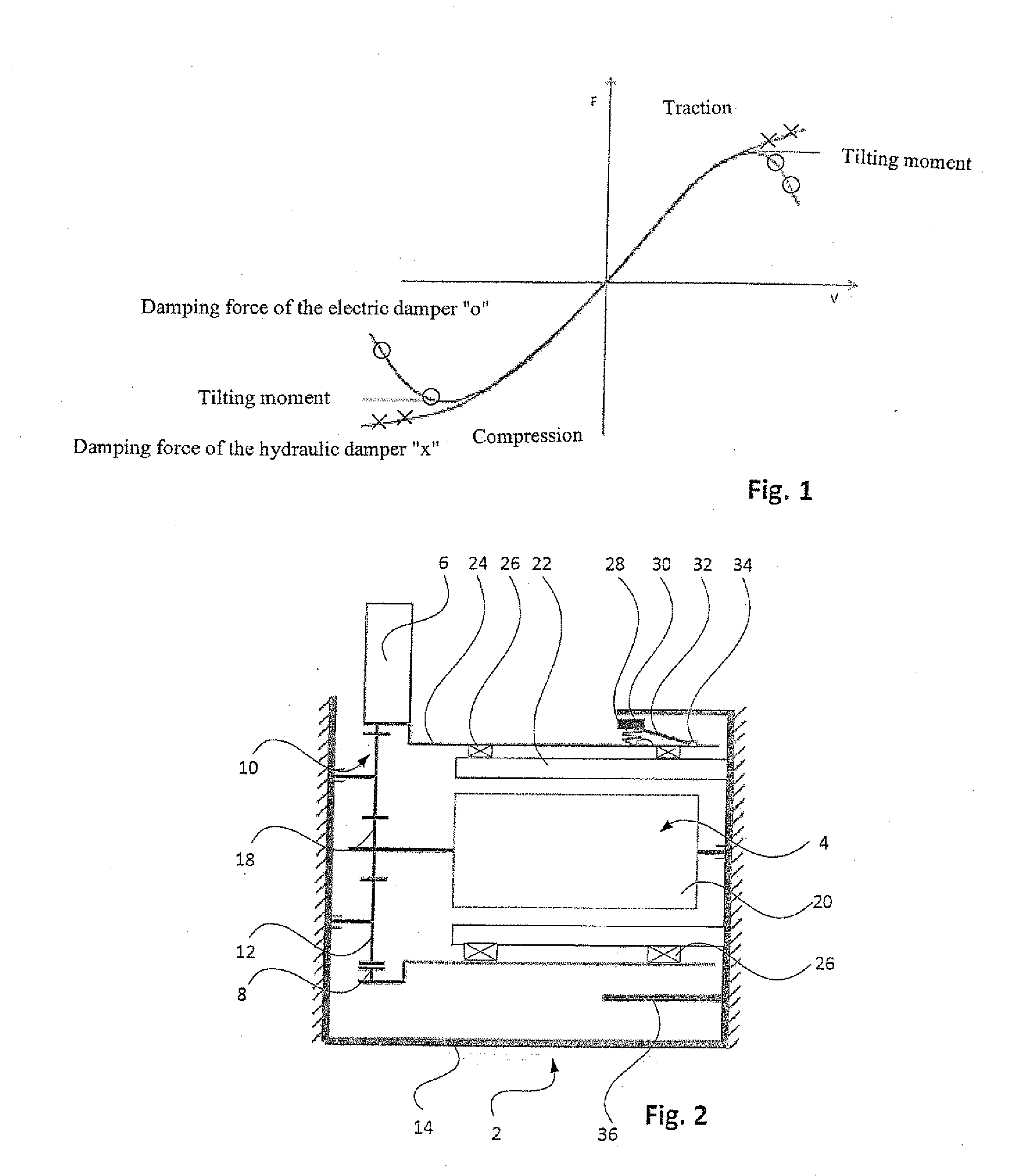
[0023]Turning now to the drawing, and in particular to FIG. 2, there is shown the functioning diagram of an electric rotational damper 2 with an electric generator 4. A coupling lever 6 of the rotational damper 2 is rigidly connected with a ring gear 8 of a planetary transmission 10. Planetary gears 12 are connected with a damper housing 14, which in turn is connected with a v...


PUM


Abstract

An electric rotational damper includes a generator which including a stator and a rotor; a damper housing having a housing attachment, wherein the stator is connected with the damper housing, and wherein the housing attachment and the stator in fixed rotative relationship with the damper housing; a transmission connecting a coupling lever with the rotor of the transmission of the rotational damper; a housing part connected with and co-rotating with the transmission, wherein the housing part is in surrounding relationship with the rotor, and wherein the housing attachment is in surrounding relationship with the housing part; and a centrifugal brake arranged between the housing part and the housing attachment.

Description

CROSS-REFERENCES TO RELATED APPLICATIONS[0001]This application claims the priority of German Patent Application, Serial No. 10 2013 004 956.3, filed Mar. 22, 2013, pursuant to 35 U.S.C. 119(a)-(d), the disclosure of which is incorporated herein by reference.BACKGROUND OF THE INVENTION[0002]The present invention relates to a rotational damper with a housing- fixed stator, a rotor and a transmission, which connects an coupling lever with the rotor of the transmission of the rotational damper.[0003]The following discussion of related art is provided to assist the reader in understanding the advantages of the invention, and is not to be construed as an admission that this related art is prior art to this invention.[0004]WO 2011 / 042085 A1 relates to an electric damper for damping relative movements between a first and a second mass, including a generator which is driven by the movement of the mass, and which is characterized in that the generator is integrated into a transmission, wherei...

Claims


Application Information

Patent Timeline
IPC IPC(8): H02K7/102
CPCH02K7/102B60G13/14F16F15/035F16F15/1202F16F15/129B60G2300/60
Inventor WILLEMS, MARCO
Owner AUDI AG
Why Eureka
Try Eureka