Magnet-embedded rotor, method for manufacturing magnet-embedded rotor, and orientation and magnetization device

Inactive Publication Date: 2014-09-25
JTEKT CORP
View PDF17 Cites 7 Cited by
  • Summary
  • Abstract
  • Description
  • Claims
  • Application Information

AI Technical Summary

Benefits of technology

[0019]According to the configuration, the magnetic flux generated by the magnetic flux generating unit can be collected by the magnetizing yoke and supplied to the projecting portion, and thus the quantity of the magnetic flux supplied to the projecting portion can be increased as compared to a case where the magnetic flux generating unit directly faces the outer peripheral side surface and the circumferential d

Problems solved by technology

The quantity of the magnetic flux per unit area that can be supplied from the magnetization device is limited.
Accordingly, in a case where an area of the outer peripheral surface of the rotor core receiving the supply of the magnetic flux from the magnetization device is small with respect to an area of a magnetization surface of the magnet material, ma

Method used


Image

  • Magnet-embedded rotor, method for manufacturing magnet-embedded rotor, and orientation and magnetization device
  • Magnet-embedded rotor, method for manufacturing magnet-embedded rotor, and orientation and magnetization device
  • Magnet-embedded rotor, method for manufacturing magnet-embedded rotor, and orientation and magnetization device

Examples


Example

[0036](First Embodiment) Hereinafter, a magnet-embedded rotor according to a first embodiment will be described. Firstly, a structure of an IPM motor that uses the magnet-embedded rotor according to the present embodiment will be described.

[0037]As illustrated in FIG. 1, the IPM motor includes a stator 2 that is fixed to an inner peripheral surface of a housing 1, a motor shaft 3 as a rotating shaft that is supported so as to be rotatable around an axis m, by the housing 1 via a bearing (not illustrated), and a rotor 4 that is integrally fitted to an outer periphery of the motor shaft 3 and is arranged inside the stator 2.

[0038]The stator 2 is formed to be cylindrical around the axis m. The stator 2 has a structure in which a plurality of magnetic steel sheets are stacked in an axial direction of the stator 2. Six teeth 20 that extend toward a radial direction inner side are formed on an inner peripheral surface of the stator 2. A stator coil 21 is wound around each of the teeth 20....

Example

MODIFICATION EXAMPLE

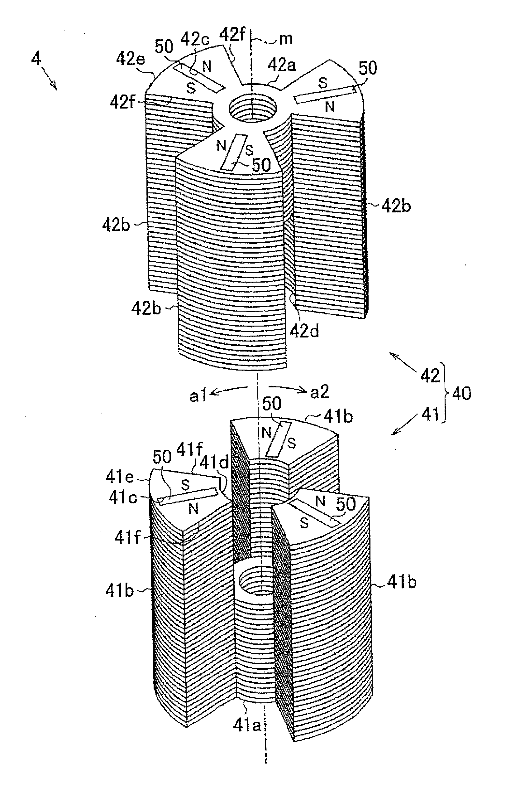
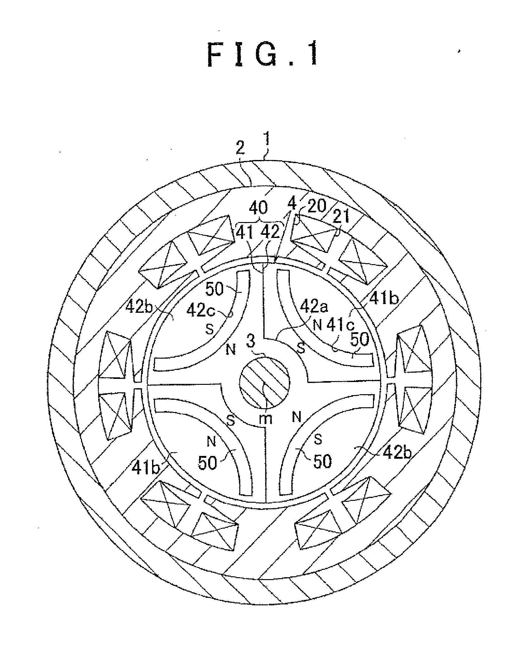
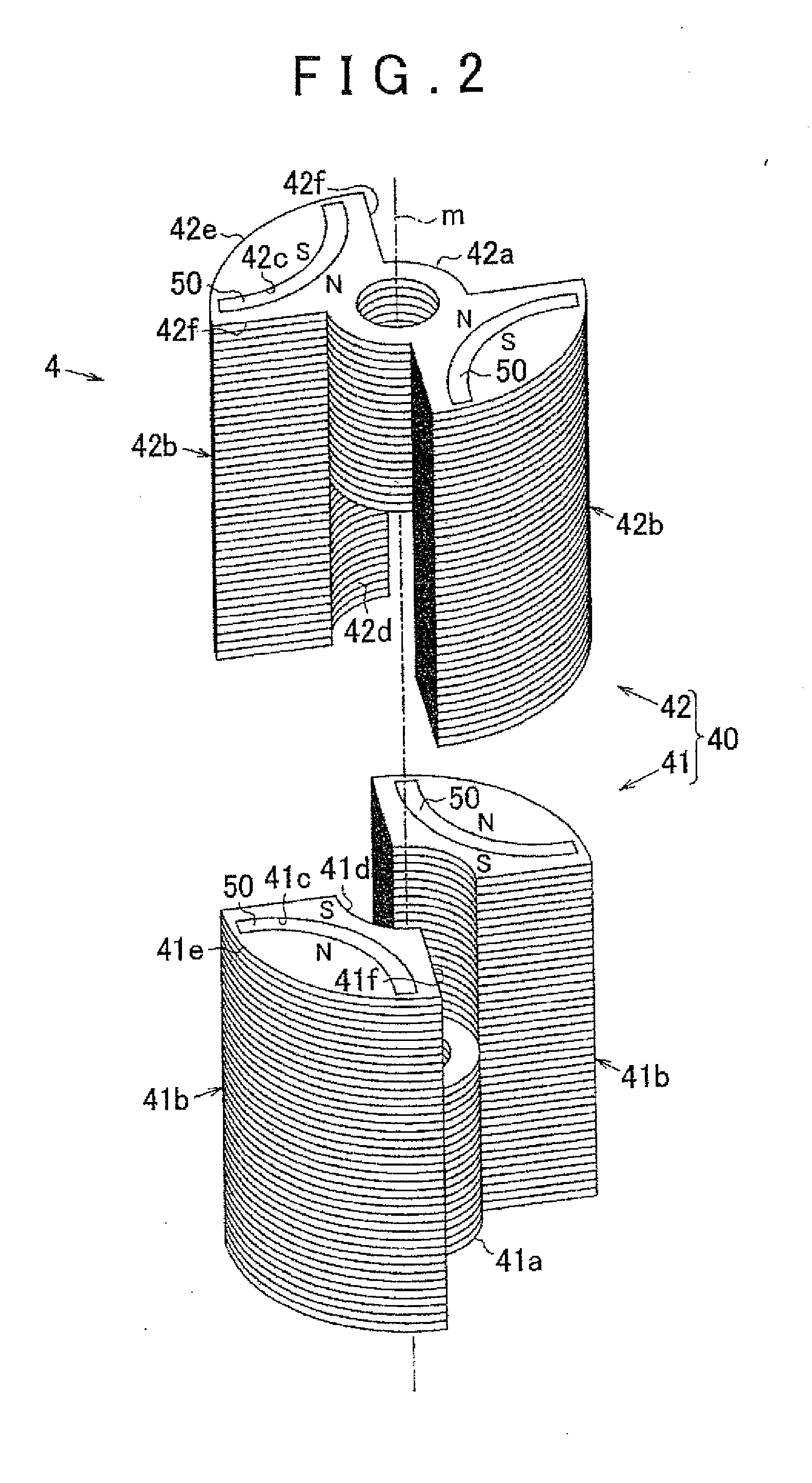
[0051]Next, a modification example of the magnet-embedded rotor 4 according to the first embodiment will be described. As illustrated in FIG. 6, in this modification example, three substantially fan-shaped projecting portions 41b are formed at equal angular intervals at an outer peripheral part of the tubular portion 41a of the first core member 41. Similarly, three substantially fan-shaped projecting portions 42b are formed at equal angular intervals at an outer peripheral part of the tubular portion 42a of the second core member 42. The rotor 4 that has six magnetic poles can be formed by assembling the first core member 41 and the second core member 42. When the number of projecting portions 41b, 42b of the core members 41, 42 is changed appropriately in this manner, the number of magnetic poles of the rotor 4 can be changed with ease.

[0052]Next, a method for manufacturing the rotor 4 illustrated in FIG. 6 will be described. As in the first embodiment, the fi...

Example

[0057](Second Embodiment) Next, a magnet-embedded rotor according to a second embodiment will be described. The following description focuses on differences between the second embodiment and the modification example of the first embodiment.

[0058]As illustrated in FIG. 8, in the second embodiment, a cross-sectional shape of the magnet insertion hole 41c formed in the projecting portion 41b of the first core member 41 that is orthogonal to the tubular portion axial direction is a rectangular shape extending in the tubular portion radial direction. Similarly, a cross-sectional shape of the magnet insertion hole 42c formed in the projecting portions 42b of the second core member 42 that is orthogonal to the tubular portion axial direction is a rectangular shape extending in the tubular portion radial direction. The permanent magnet 50 whose cross-sectional shape that is orthogonal to the tubular portion axial direction is a rectangular shape is inserted into each of the magnet insertion...


PUM


Abstract

A magnet-embedded rotor includes a cylindrical rotor core that rotates together with a rotating shaft; and permanent magnets embedded in the rotor core. The rotor core includes core members, and each core member includes a tubular portion into which the rotating shaft is inserted and projecting portions formed to project in a radial direction of the tubular portion from an outer periphery of the tubular portion and arranged apart from each other in a circumferential direction of the tubular portion. The rotor core is formed by assembling the core members such that the tubular portions are arranged on one straight line and the projecting portion of the core member and the projecting portion of the other core member are adjacent to each other in a circumferential direction of the rotor core. The permanent magnet is embedded in each projecting portion of each core member.

Description

INCORPORATION BY REFERENCE[0001]The disclosure of Japanese Patent Application No. 2013-058085 and 2014-006890 filed on Mar. 21, 2013 and Jan. 17, 2014 including the specification, drawings and abstract is incorporated herein by reference in its entirety.BACKGROUND OF THE INVENTION[0002]1. Field of the Invention[0003]The invention relates to a magnet-embedded rotor, a method for manufacturing a magnet-embedded rotor, and an orientation and magnetization device.[0004]2. Description of Related Art[0005]Interior permanent magnet motors (IPM motors) having a structure in which a permanent magnet for a field is embedded in a rotor are known. A method described in Japanese Patent Application Publication No. 2010-193587 (JP 2010-193587 A) is an example of known methods for manufacturing a magnet-embedded rotor used in the IPM motor. In JP 2010-193587 A, a magnet material prior to magnetization is embedded in a magnet insertion hole that is formed in a cylindrical rotor core, and then a magn...

Claims


Application Information

Patent Timeline
IPC IPC(8): H02K1/27
CPCH02K1/27H02K1/2766H02K15/03H02K1/28H02K1/276
Inventor NIMURA, KEITAKANDA, NAOTAKEYAMAGUCHI, RYOSUKE
Owner JTEKT CORP
Why Eureka
Try Eureka