Fuel cell system

Active Publication Date: 2019-08-22
HONDA MOTOR CO LTD
View PDF0 Cites 3 Cited by
  • Summary
  • Abstract
  • Description
  • Claims
  • Application Information

AI Technical Summary

Benefits of technology

[0005]In the fuel cell system of this type, at the time of regenerating electrical energy at the motor, power consumption control is performed for consuming redundant electrical energy which cannot b

Problems solved by technology

As a result, fuel economy is degraded, unwanted noises are g

Method used


Image

  • Fuel cell system
  • Fuel cell system
  • Fuel cell system

Examples


Embodiment Construction

[0026]Hereinafter, a preferred embodiment of the present invention will be described with reference to the accompanying drawings.

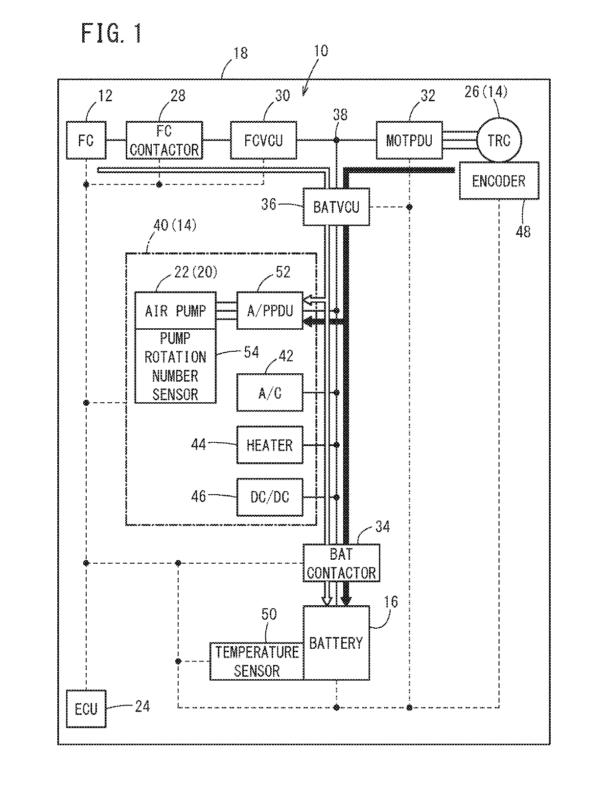
[0027]A fuel cell system 10 according to an embodiment of the present invention in FIG. 1 is a system for supplying electrical energy using a fuel cell 12 (hereinafter also referred to as the FC 12). For example, electrical energy generated by power generation of the FC 12 is supplied to load(s) 14 and / or a battery 16 (energy storage), and regenerative electrical energy (regenerative power) of the load 14 is supplied to the battery 16. The fuel cell system 10 is mounted in a fuel cell vehicle 18 (hereinafter simply referred to as the vehicle 18).

[0028]The FC 12 of the fuel cell system 10 has stack structure. In the FC 12, reactions of hydrogen and oxygen are induced, and electrical energy produced in the reactions is output to the outside of the FC 12. To this end, the fuel cell system 10 includes a hydrogen gas supply apparatus (not shown) for supplying a...


PUM


Abstract

A fuel cell system includes a FC, a TRC, an oxygen-containing gas supply apparatus, a battery, and an ECU. The ECU is capable of performing power consumption control which allows the oxygen-containing gas supply apparatus to consume electrical energy during regeneration of the TRC. The ECU is configured to determine a charge margin with respect to a charge limitation value of the battery, in a manner that the charge margin set after the power consumption control starts becomes smaller than the charge margin set before the power consumption control is performed.

Description

CROSS-REFERENCE TO RELATED APPLICATION[0001]This application is based upon and claims the benefit of priority from Japanese Patent Application No. 2018-025879 filed on Feb. 16, 2018, the contents of which are incorporated herein by reference.BACKGROUND OF THE INVENTIONField of the Invention[0002]In structure including a fuel cell, an electric motor, and a battery, the present invention relates to a fuel cell system for controlling the charging state of the battery.Description of the Related Art[0003]As disclosed in Japanese Laid-Open Patent Publication No. 2017-152280, in a fuel cell system, a battery (energy storage) is connected in parallel between a fuel cell and a motor (electric motor), and the battery is charged with electrical energy generated by the fuel cell and regenerative electrical energy generated by the motor. When generated electrical energy is not sufficient, the battery supplies electrical energy. Further, auxiliary devices such as an air pump are connected in para...

Claims


Application Information

Patent Timeline
IPC IPC(8): B60L58/30H01M10/44B60L58/40H01M8/04537H01M8/04828
CPCB60L58/30H01M10/44B60L58/40H01M8/04619H01M8/0494H01M2250/20H02J2001/004H01M8/04298H01M8/04947H01M8/04201H01M8/04089H01M16/006H02J7/1423H02J2300/30H02J2310/48Y02T90/14Y02T10/7072Y02E60/10
Inventor TAKAMOTO, SHINGOFUTATSUDERA, AKIOMATSUI, AKIHIROOJIMA, KUNIAKINAKAGAWA, TAKUTOSHIRASAKA, TAKUYAHIGASHITANI, KOSUKE
Owner HONDA MOTOR CO LTD
Why Eureka
Try Eureka