Chair and supports

Active Publication Date: 2014-10-02
FORMWAY FURNITURE
View PDF1 Cites 29 Cited by
  • Summary
  • Abstract
  • Description
  • Claims
  • Application Information

AI Technical Summary

Benefits of technology

The present invention provides a chair with a recline mechanism that lifts the seat portion upon reclining of the back portion. The recline mechanism includes a seat portion, a back portion, and a recline link pivotally connected to the seat portion and the back portion. The recline link is connected to the seat portion and the back portion at a position above the lower end of the back portion. The recline mechanism is designed to provide a smooth and comfortable reclining experience for the chair occupant.

Problems solved by technology

Traditional reclining and / or rocking chairs are often large, heavy chairs that take up significant room.
However, those chairs often have basic mechanisms that only provide limited functionality in the chair.
Those reclining chairs have a less than optimal relationship between the seat and back.
When the back of the chair is reclined, the relationship between the seat and back will generally be such that the user will not be comfortable in the chair, particularly over long periods.
Such chairs also do not have built in extendible leg rests or supports, due to the lack of housing to hide the mechanisms of such supports.
This means the head rest adjustment is a two step process, and reduces the likelihood of the headrest position being adjusted.
As a result, people may be inclined to use the head rests in a less than optimal position.
Often, the user will not be able to adjust the head rest whilst seated due to high friction mechanisms and twin action adjusters, which means the user cannot switch between different head rest positions as needed when moving the chair between upright and reclined positions or when changing between tasks such as watching television and working on a laptop computer.
However, those arrangements typically only provide two or three discrete adjustment positions.
A user may not be provided with optimal comfort with that restricted number of adjustment positions.

Method used


Image

  • Chair and supports
  • Chair and supports
  • Chair and supports

Examples


Embodiment Construction

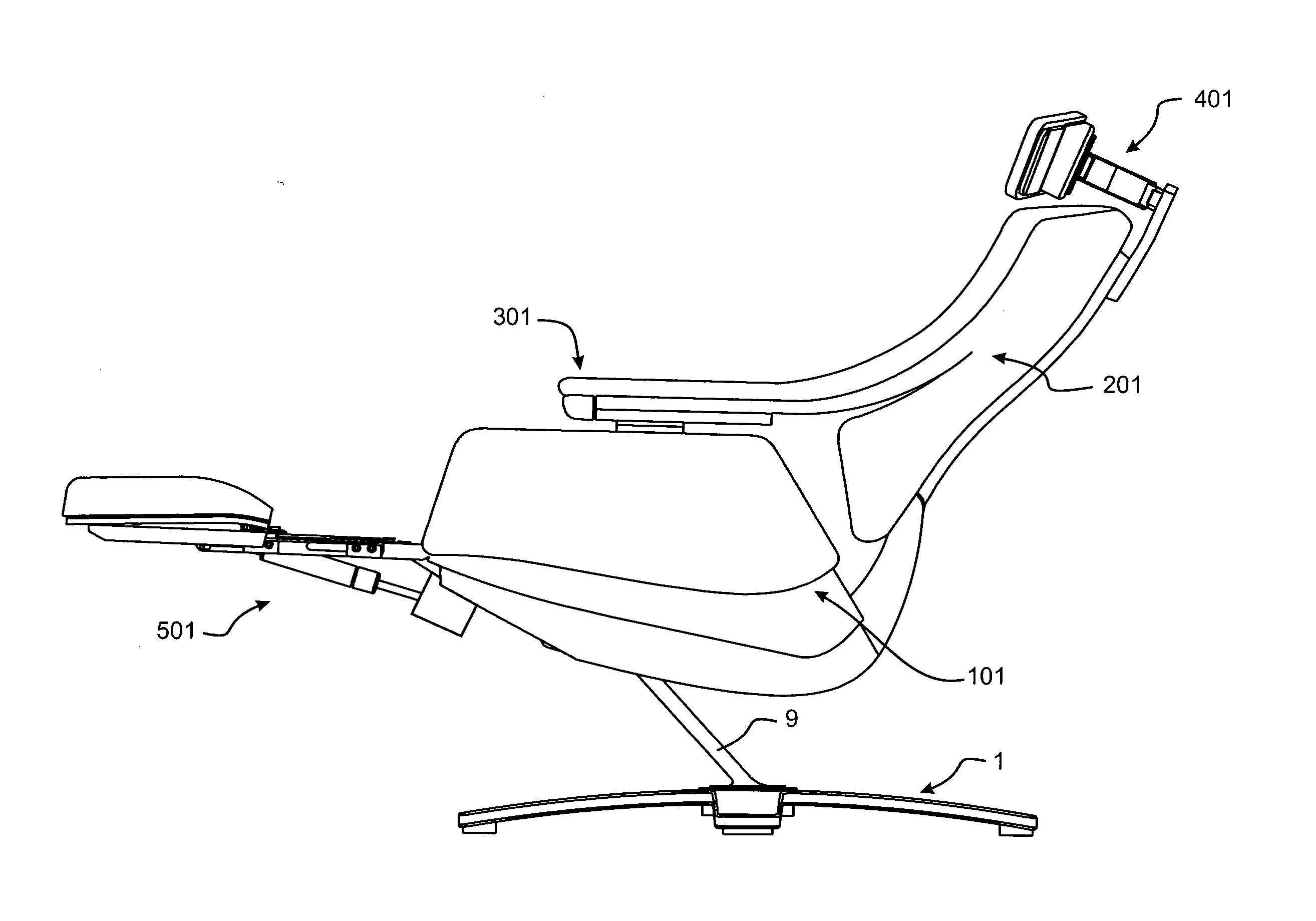
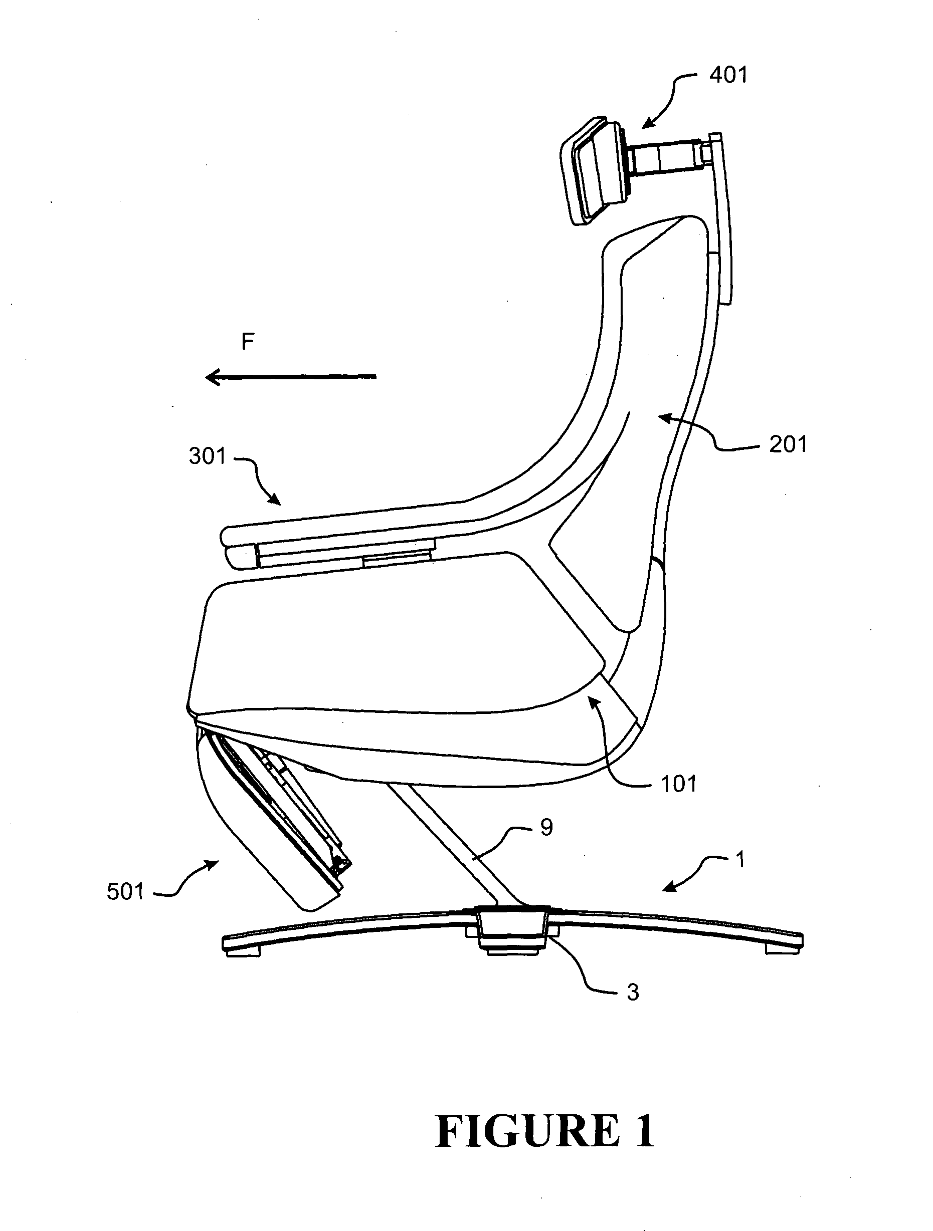
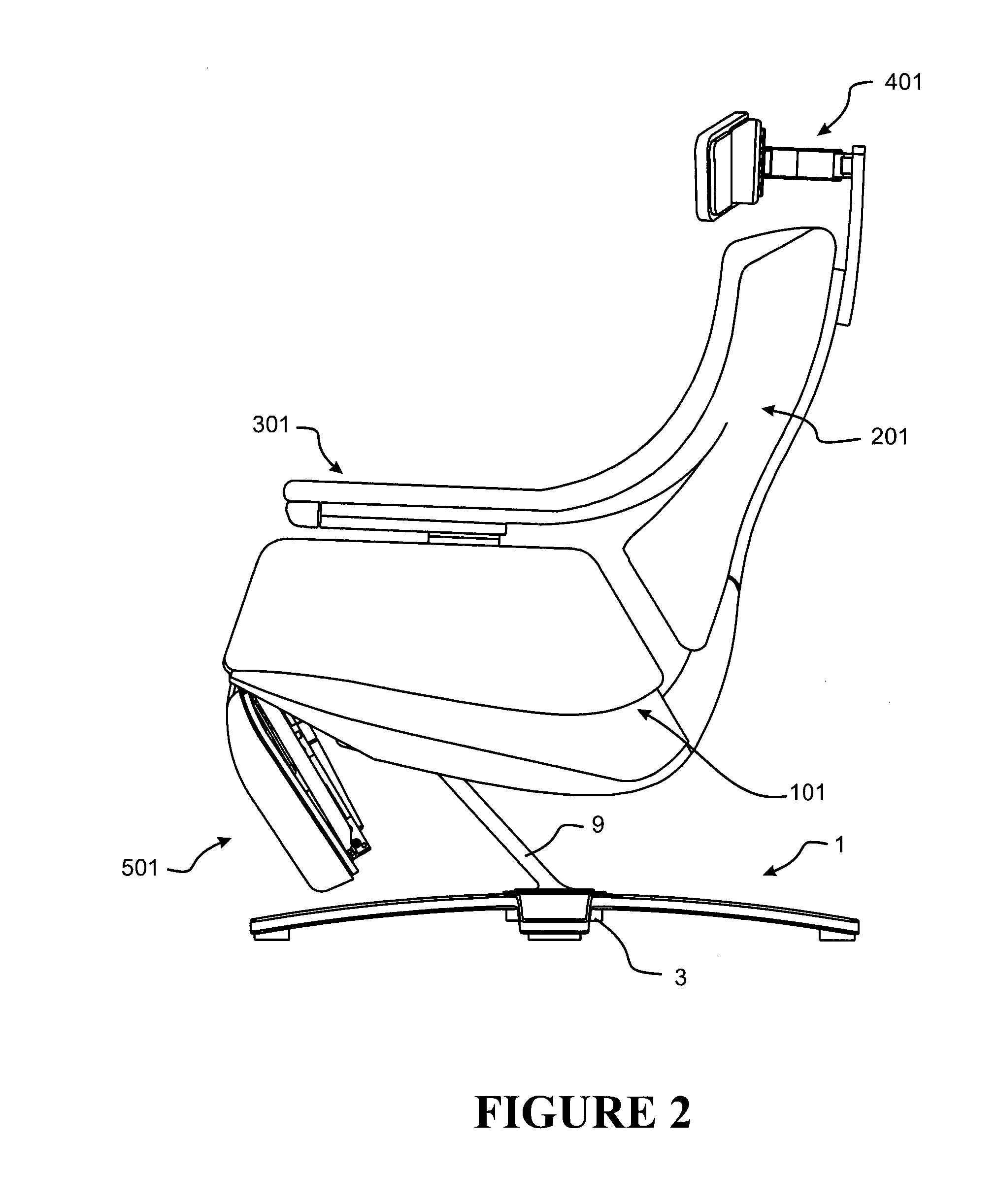
[0194]FIGS. 1 to 8 show a reclining domestic lounger chair according to a preferred embodiment of the present invention. The chair comprises a supporting frame 1 including a base assembly 3, a seat portion 101 for supporting a seated occupant, a back portion 201 for supporting the back of a seated occupant, arm rests 301 for supporting the arms of a seated occupant, an adjustable head or neck rest or support assembly 401 and an extendable and retractable foot or leg rest or support assembly 501.

[0195]The chair additionally has a recline mechanism configured to lift the seat portion 101 relative to an intermediate support of the supporting frame 1 upon a reclining action of the back portion 201, and a rocker mechanism that operatively connects a main transom of the supporting frame and the intermediate support of the supporting frame, to provide a rocking motion therebetween. These features will be described in further detail below.

[0196]The mechanisms and features operate together t...


PUM


Abstract

A chair has a supporting frame 1, a seat portion 101, a back portion 201 that has an upper end, a lower end, and is pivotally mounted relative to the supporting frame at a position above its lower end, and a recline mechanism 601. The recline mechanism 601 lifts the seat portion 101 upon a reclining action of the back portion 201, and has an operative connection 603, 611 between the seat portion and the supporting frame and a drag link 602 pivotally connected to the seat portion 101 and pivotally connected to the back portion 201 at a position below the pivotal mounting of the back portion relative to the supporting frame. As the back portion 201 of the chair is reclined, the lower end of the back portion 201 moves forward and the drag link 602 pulls the seat portion 101 upward relative to the supporting frame 1.

Description

FIELD OF THE INVENTION[0001]The invention relates generally to chairs and supports for use in chairs. More particularly, although not exclusively, the invention relates to reclining and rocking chairs suitable for domestic lounge use.BACKGROUND TO THE INVENTION[0002]Traditional reclining and / or rocking chairs are often large, heavy chairs that take up significant room. They also often have large housings that extend substantially to the floor to hide bulky mechanisms that provide the rocking and / or reclining action of the chairs. Such chairs often have extendible leg rests or supports which have bulky mechanisms, which again must be hidden in the large housings of the chair for aesthetic purposes and to hide potential pinch points from users.[0003]In more recent times, lighter weight reclining lounge chairs have become available that do not have the large housings. Such chairs are generally mounted on pedestals. However, those chairs often have basic mechanisms that only provide lim...

Claims


Application Information

Patent Timeline
IPC IPC(8): A47C1/032A47C7/40A47C7/38A47C7/02A47C3/02A47C7/50
CPCA47C7/38A47C7/54A47C1/032A47C3/0255A47C7/40A47C1/03294A47C3/02A47C7/02A47C7/506A47C1/031A47C7/44A47C7/4454A47C7/5068A47C1/0342A47C7/445
Inventor PARKER, KENT WALLACEBAUM, GREGORY WILLIAMSTEWART, LYALL DOUGLASBATEMAN, GAVIN JAMESCRAZE, LEON HARLEYFIFIELD, JON LEONARDPENNINGTON, MARK RUNDLEO'HARA, WAYNE DOUGLASCOLLINGS, MARTYN WALTER GOODWINSTEVENSON, PAUL JAMES
Owner FORMWAY FURNITURE
Why Eureka
Try Eureka