Mower with integrated occupant presence and independent drive and brake lockout

Inactive Publication Date: 2006-02-28
CLARK EQUIP CO INC
View PDF12 Cites 8 Cited by
  • Summary
  • Abstract
  • Description
  • Claims
  • Application Information

AI Technical Summary

Benefits of technology

[0009]In another embodiment of the present invention, a lawn mower having a drive mechanism configured to drive a shaft in a first and second direction is disclosed. A drum pulley is coupled to the shaft. A drive wheel is coupled to the drum pulley by a flexible member or flexible drive belt. A tensioning system is configured to apply tension to a first slack si

Problems solved by technology

Because these machines typically weigh several hundred pounds, it would be labor intensive, if not impossible, to operate and maneuver the turf care machines in such a manner for extensive periods of time without some type of operator assist device.
While both hydraulic and mechanical drive mechanisms have been commonly used in the past, belt driven drive mechanisms are being implemented in walk-behind turf care machines on an ever increasing basis due to the decrease in price and known reliability of such systems.
While present belt driven drive operator control systems such as those described above exhibit sufficient performance characteristics, such systems require numerous linkages between the components to implement, thus increasing turf care machine cost.

Method used


Image

  • Mower with integrated occupant presence and independent drive and brake lockout
  • Mower with integrated occupant presence and independent drive and brake lockout
  • Mower with integrated occupant presence and independent drive and brake lockout

Examples


Embodiment Construction

[0025]The following description of the preferred embodiment is merely exemplary in nature and is in no way intended to limit the invention, its application, or uses.

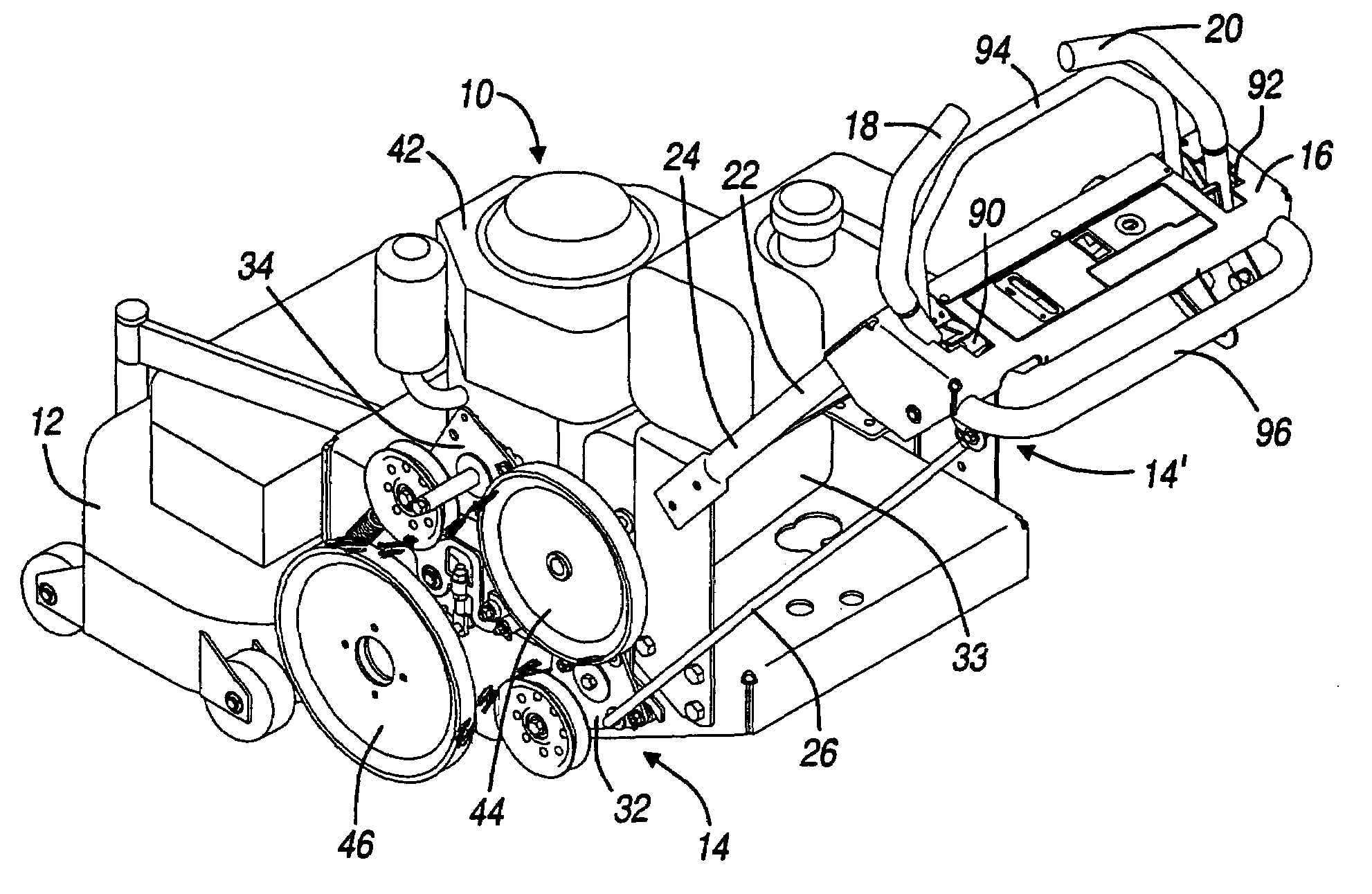
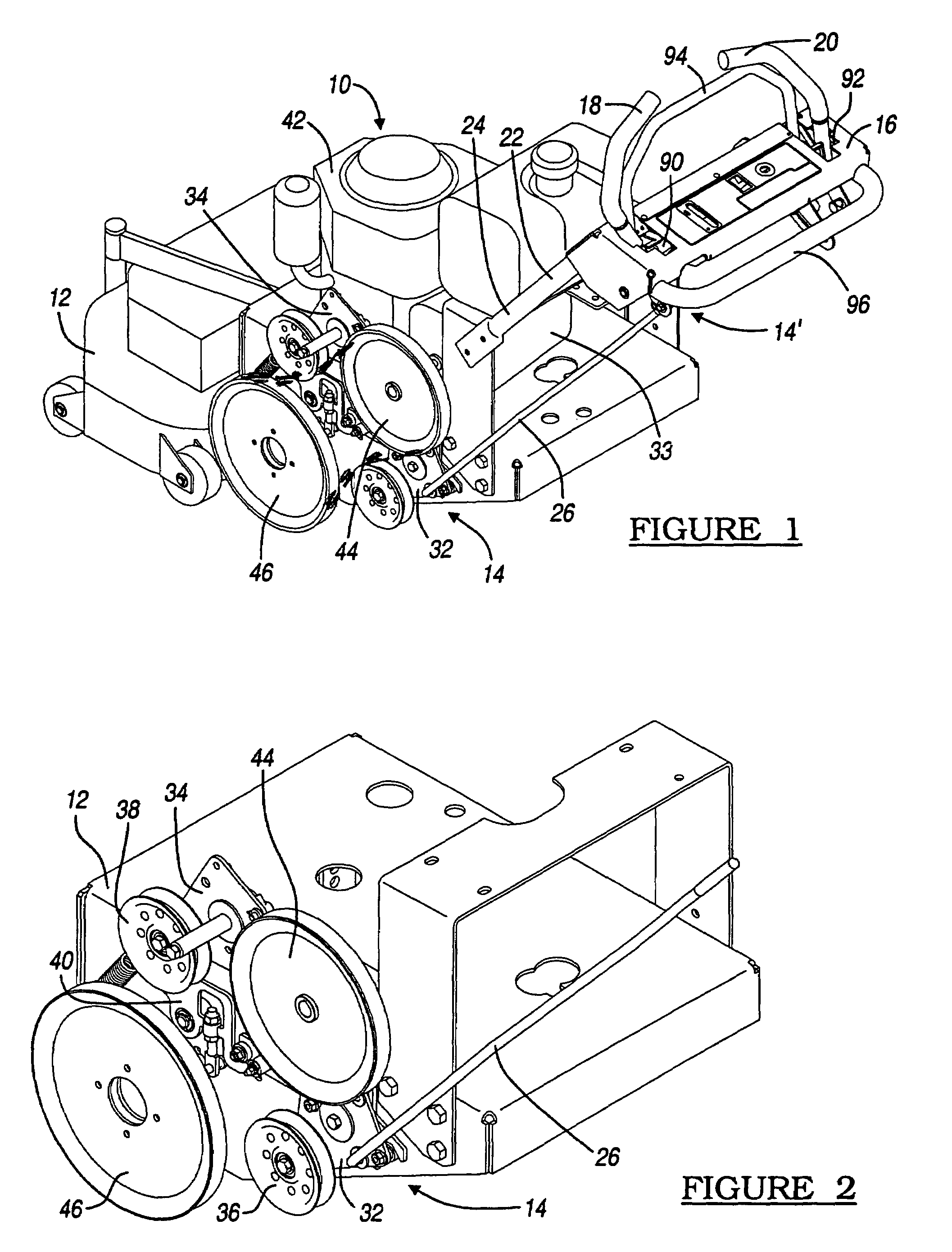
[0026]FIG. 1 represents a perspective view according to the teachings of the present invention. Shown is a mower 10 having a support structure 12, drive mechanism 14, control panel 16, and a pair of handles 18 and 20. Disposed between the support structure 12 and the control panel 16 is a support structure 22 having a pair of support bars 24 and a control mechanism 26.

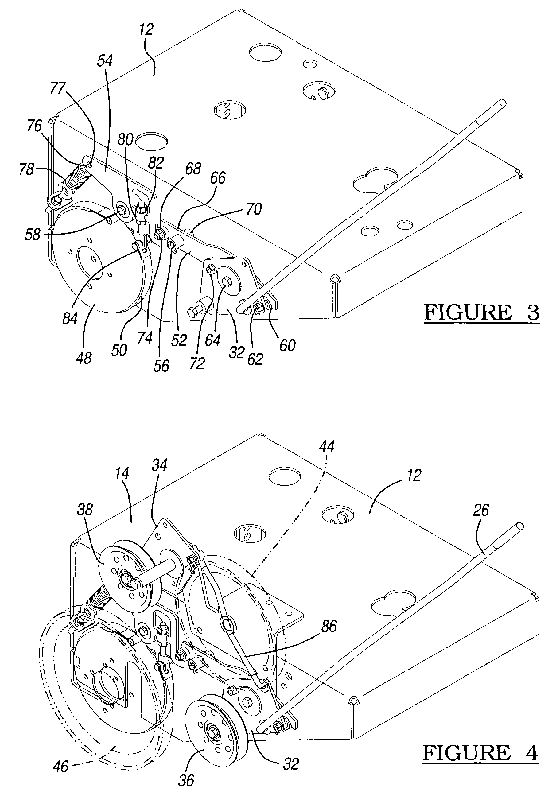
[0027]The handles 18 and 20 of control panel 16 functions to regulate the drive mechanisms 14 and 14′ and the left and rear wheels 28 and 30. The control mechanism 26 controls the drive mechanism 14 by regulating the movement of an idler mechanism 31, which has first and second idler arms or plates 32 and 34. As further described below, the idler arms 32 and 34 regulate the movement of the idler pulleys 36 and 38 and braking mechanism 40.

[0028]The drive mec...


PUM


Abstract

Disclosed is a lawn mower device having a drive configured to rotate a shaft in a first and second direction. A drive wheel is coupled to the shaft and is coupled to a driven wheel by a drive belt. A tensioning system is shown coupled to the drive belt. The tensioning system has a first idler plate configured to bias a first idler pulley against the drive belt when the drive is rotating the shaft in the first direction and a second idler plate configured to bias a second idler plate against the drive belt when the drive is rotating the shaft in a second direction. A brake mechanism is further coupled to the tensioning system. The brake mechanism is configured to resist the rotation of the driven wheel.

Description

FIELD OF THE INVENTION[0001]The present invention relates to a drive mechanism for a walk behind lawn mower and, more particularly, to a zero turn radius drive mechanism having incorporated forward / reverse and braking features incorporated into a belt driven drive system.BACKGROUND OF THE INVENTION[0002]Conventional commercial walk-behind turf care machines, such as walk-behind lawnmowers include a number of levers and linkages used to control machine operation. During routine operation, these machines must often be maneuvered around trees, flower beds and other obstacles quickly and with precision. Because these machines typically weigh several hundred pounds, it would be labor intensive, if not impossible, to operate and maneuver the turf care machines in such a manner for extensive periods of time without some type of operator assist device.[0003]Therefore, commercial turf care machines are typically equipped with self-propelling drive mechanisms for driving the wheels of the mac...

Claims


Application Information

Patent Timeline
IPC IPC(8): A01D69/00A01D34/47
CPCA01D34/475
Inventor NESHEIM, JEFFREY C.
Owner CLARK EQUIP CO INC
Why Eureka
Try Eureka