
Anti-rotation device for electrical connectors

Inactive Publication Date: 2014-12-11
ALCATEL LUCENT SAS
View PDF7 Cites 1 Cited by
  • Summary
  • Abstract
  • Description
  • Claims
  • Application Information

AI Technical Summary

Benefits of technology

The invention is a device to prevent two electrical connectors from spinning and separating during use. It is designed to stop this issue by engaging with the male and female threads of the connectors, and stopping rotation of the nut with female threads. This stops the connectors from becoming separated and can help to improve the reliability of the electrical connection.

Problems solved by technology

Unfortunately, even when the specified torque value is applied to the hex nut, stress, thermal shock, and vibration due to, for example, shipping of the mated connector pair, can cause the hex nut to back out, thereby losing the specified torque value.
This, in turn, can jeopardize the proper electrical coupling of the connectors in a connector pair.
However, connector pairs having higher specified torque values are typically more expensive than connector pairs having lower specified torque values.
Therefore, using connector pairs having higher specified torque values is disadvantageous because such connector pairs increase costs.

Method used


Image

  • Anti-rotation device for electrical connectors
  • Anti-rotation device for electrical connectors
  • Anti-rotation device for electrical connectors

Examples


Embodiment Construction

[0024]Reference herein to “one embodiment” or “an embodiment” means that a particular feature, structure, or characteristic described in connection with the embodiment can be included in at least one embodiment of the disclosure. The appearances of the phrase “in one embodiment” in various places in the specification are not necessarily all referring to the same embodiment, nor are separate or alternative embodiments necessarily mutually exclusive of other embodiments. The same applies to the term “implementation.”

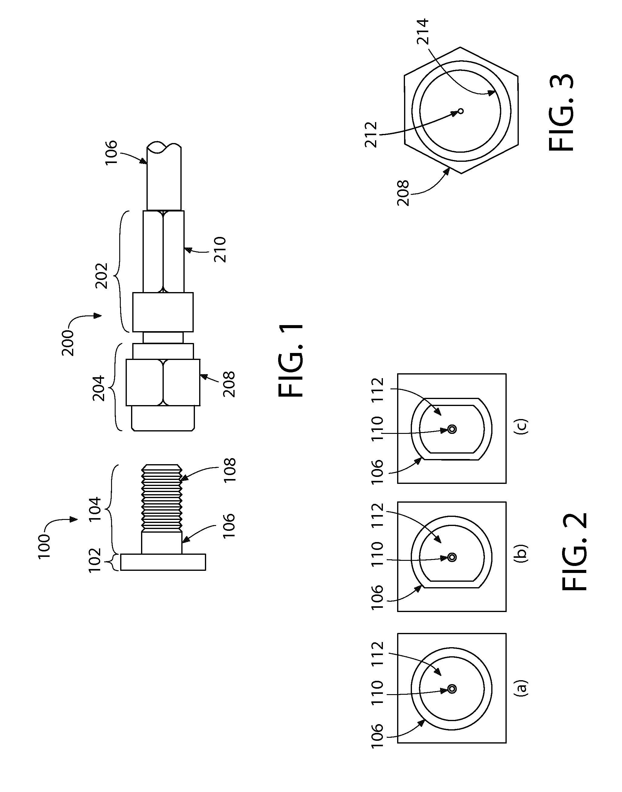
[0025]FIG. 1 shows a side view of one implementation of a conventional radio-frequency (RF) coaxial connector pair. The connector pair is a sub-miniature version A (SMA)-type connector pair having a first connector 100 and a corresponding second connector 200. First connector 100 comprises (i) a device-side portion 102 that is configured to mate either directly with an RF device (not shown) or with a cable leading to an RF device (also not shown) and (ii) a connector-side ...


PUM


Abstract

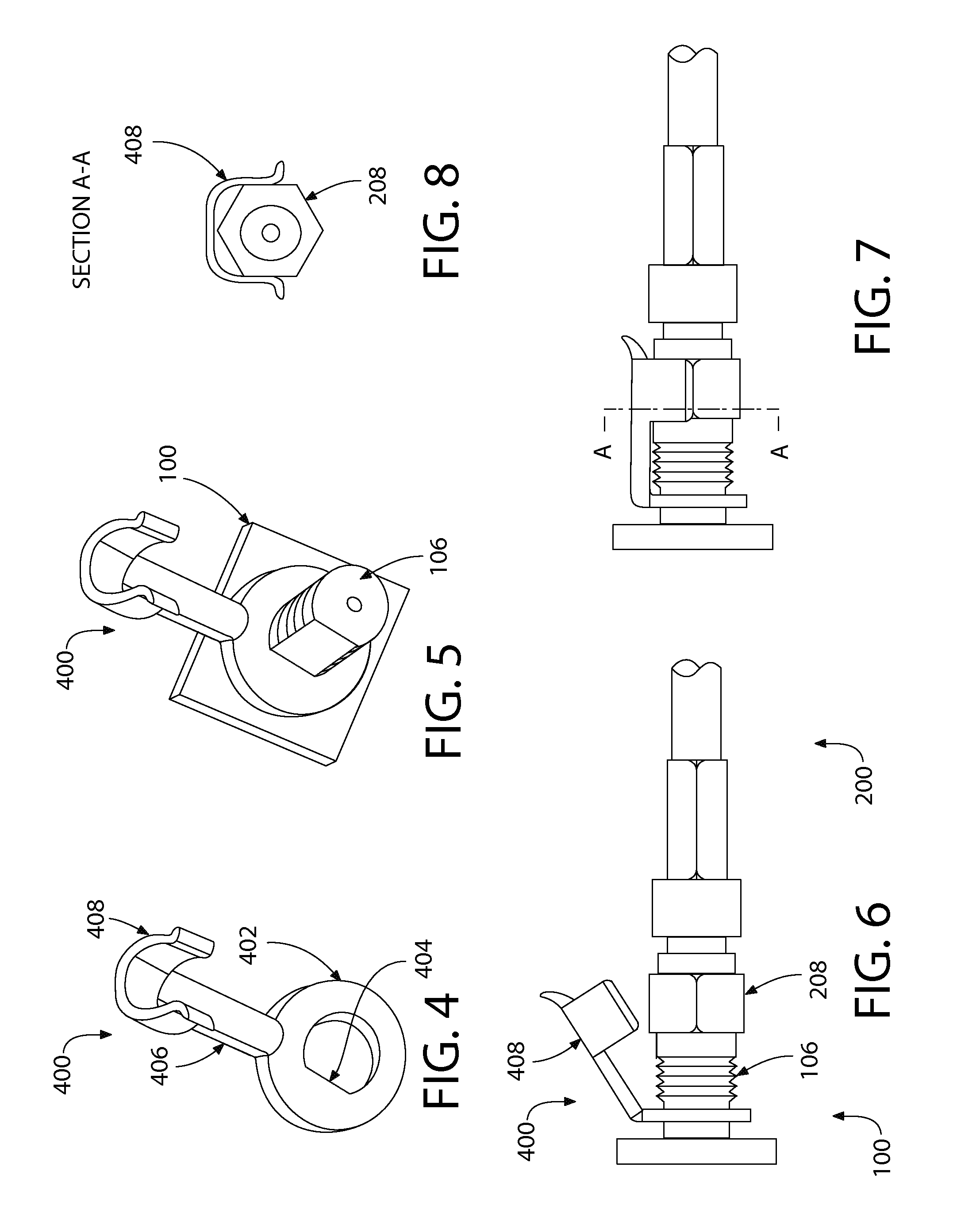
In one embodiment, an anti-rotation device is designed to prevent de-coupling of an electrical connector pair. The connector pair includes (i) a first electrical connector having a barrel with male threads formed thereon and (ii) a second electrical connector having a nut with female threads formed therein that mate with the male threads of the first connector. The anti-rotation device includes a barrel-locking portion connected by an interconnecting portion to a nut-locking portion. The barrel-locking portion engages the barrel of the first electrical connector to prevent rotation of the anti-rotation device circumferentially around the barrel. The nut-locking portion engages the nut of the second electrical connector to prevent the nut from rotating and backing out. The anti-rotation device inhibits rotation of the nut relative to the barrel, thereby preventing de-coupling of the second electrical connector from the first electrical connector.

Description

BACKGROUND[0001]1. Field of the Invention[0002]The present invention relates to electrical connectors, and, more specifically but not exclusively, preventing de-coupling of electrical connectors.[0003]2. Description of the Related Art[0004]In radio-frequency (RF) coaxial connector pairs that employ a hexagonal (hex) nut to secure one connector of the pair to the other, the hex nut may be turned using a controlled metered tool until a specified torque value is reached. For example, in SMA-type connectors, the specified torque value may range from 8-10 inch-pounds, which is slightly above the torque obtainable by the human hand. Unfortunately, even when the specified torque value is applied to the hex nut, stress, thermal shock, and vibration due to, for example, shipping of the mated connector pair, can cause the hex nut to back out, thereby losing the specified torque value. This, in turn, can jeopardize the proper electrical coupling of the connectors in a connector pair.[0005]To p...

Claims


Application Information

Patent Timeline
IPC IPC(8): H01R13/622
CPCH01R13/622H01R13/6395
Inventor MITCHELL, RAY C.PARK, JINCHUL D.
Owner ALCATEL LUCENT SAS
Learn More