Transport apparatus

Inactive Publication Date: 2018-06-14
YAMATAKE HONEYWELL CO LTD
View PDF0 Cites 0 Cited by
  • Summary
  • Abstract
  • Description
  • Claims
  • Application Information

AI Technical Summary

Benefits of technology

The present disclosure provides a transport apparatus that can move down a contact member without getting stuck or causing other problems. The inhibiting mechanism prevents the shaft from rotating when it reaches a certain position.

Problems solved by technology

However, with a rack and pinion, dust may be generated due to wear on the teeth of the rack.
Furthermore, when the rack and pinion is washed by a liquid, the liquid is unlikely to easily drain from the tooth spaces of the rack because the tooth spaces are small.
Thus, the contamination tends to remain in the rack.
Accordingly, maintenance of the rack and pinion is difficult.
When the drive mechanism for changing the level of the bar includes a motor and associated wiring, washing itself is difficult.
Also in this case, the maintenance of the rack and pinion is difficult.
Furthermore, when there is a break in the wiring, it becomes impossible to move up / down the bar.

Method used


Image

  • Transport apparatus
  • Transport apparatus
  • Transport apparatus

Examples


first embodiment

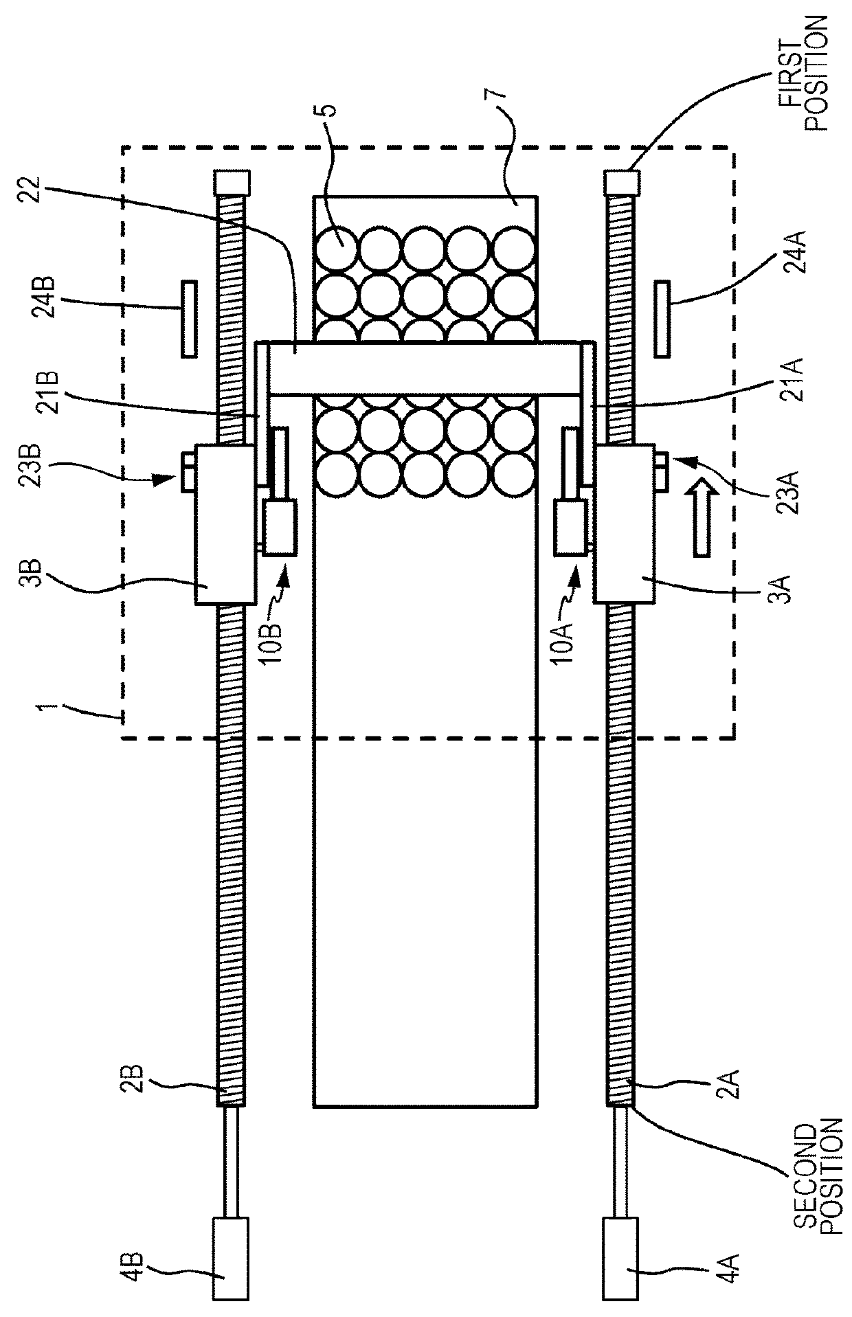
[0059]As illustrated in FIGS. 1 to 10, a transport apparatus according to a first embodiment includes moving members 3A and 3B, shafts 21A and 21B, a contact member 22, and air dampers 10A and 10B. The moving members 3A and 3B are moved along a table 7 where articles 5 are to be disposed. The shafts 21A and 21B are rotatably connected to the respective moving members 3A and 3B. The contact member 22 is connected to the shafts 21A and 21B so as to be brought into contact with the articles 5. The air dampers 10A and 10B attenuate kinetic energy of the contact member 22 and the shafts 21A and 21B while the contact member 22 and the shafts 21A and 21B are being moved down toward the table 7.

[0060]The transport apparatus according to the first embodiment may further include, for example, bar-shaped members 2A and 2B that are disposed parallel to the table 7 and include respective magnetic bodies. The moving members 3A and 3B may each include a portion that includes a magnetic body and fa...

second embodiment

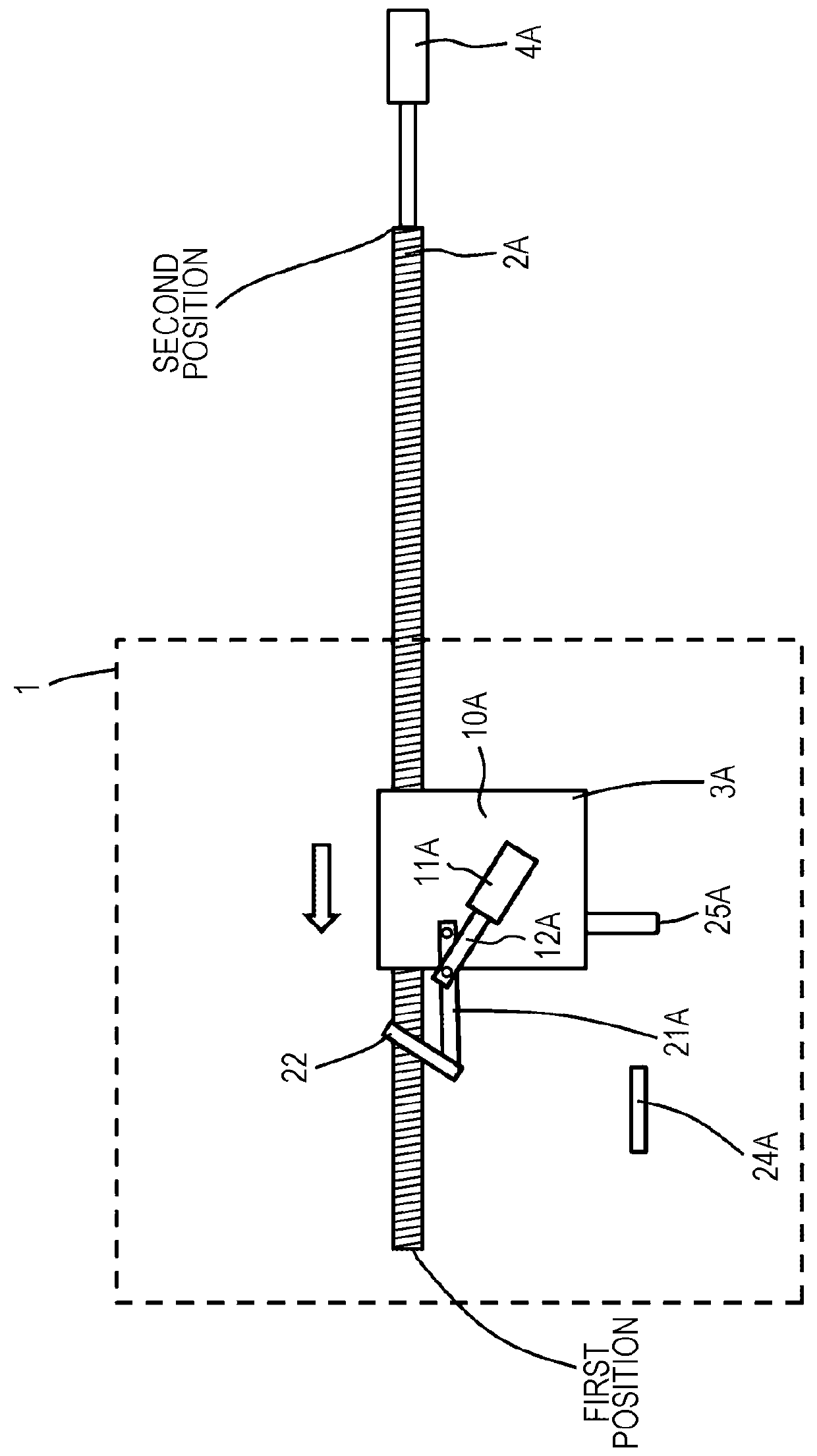
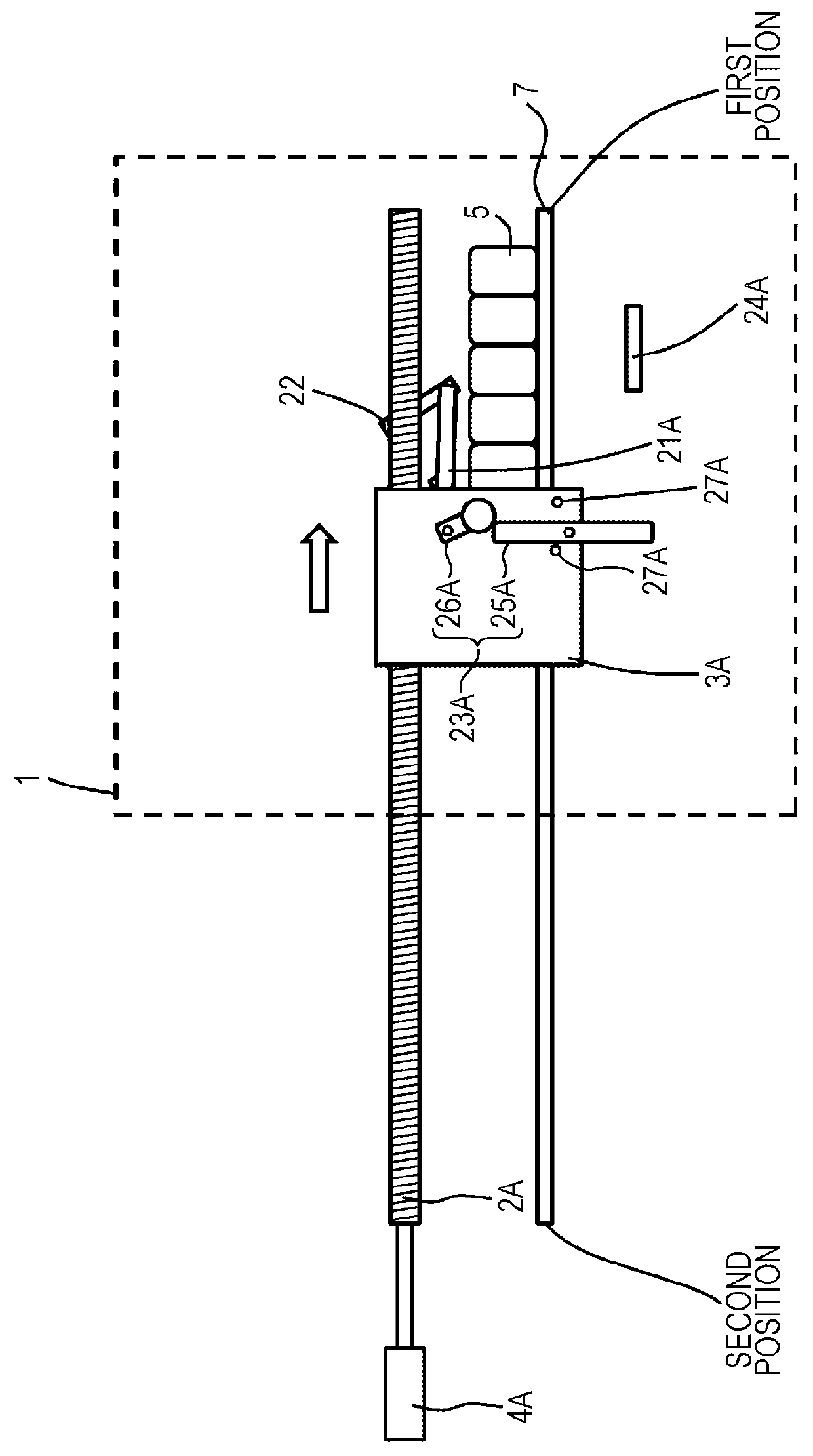
[0090]As illustrated in FIGS. 20 to 23, in the transport apparatus according to a second embodiment, the air damper 10A includes the cylinder 11A rotatably connected to the shaft 21A and the piston rod 12A at least part of which is contained in the cylinder 11A. The piston rod 12A is rotatably connected to the moving member 3A. While the contact member 22 and the shafts 21A and 21B are being moved down toward the table 7, the closed end portion of the cylinder 11A is moved toward the end of the piston rod 12A.

[0091]The air damper 10B has a structure that is the same as or similar to the structure of the air damper 10A. Other elements of the transport apparatus according to the second embodiment are the same as or similar to those of the transport apparatus according to the first embodiment. Also with the transport apparatus according to the second embodiment, the kinetic energy of the contact member 22 and the shafts 21A and 21B is attenuated, thereby the crash force of the contact ...


PUM


Abstract

A transport apparatus includes a moving member, a shaft, a contact member, and an air damper. The moving member is moved along a table where an article is to be disposed. The shaft is rotatably connected to the moving member. The contact member is connected to the shaft and is to be brought into contact with the article. The air damper attenuates kinetic energy of the contact member and the shaft while the contact member and the shaft are being moved down toward the table.

Description

CROSS-REFERENCE TO RELATED APPLICATIONS[0001]The present application is based on and claims priority to Japanese Application No. 2016-240545, filed Dec. 12, 2016, the entire contents of which are incorporated herein by reference.BACKGROUND1. Field of the Disclosure[0002]The present disclosure relates to a transport technique and in particular relates to a transport apparatus.2. Description of the Related Art[0003]In order to transport articles out of a chamber, for example, a transport apparatus provided with a bar that pushes the articles is used (see, for example, Japanese Unexamined Patent Application Publication No. 2016-90075). In another transport apparatus, a bar is inserted, for example, from the front toward the rear of the chamber, thereby the articles are pushed out of the chamber (see, for example, U.S. Pat. No. 7,695,230). While being inserted toward the rear of the chamber, the bar passes through a space above the articles. At the rear of the chamber, the bar is moved ...

Claims


Application Information

Patent Timeline
IPC IPC(8): B65G47/82F26B25/00
CPCB65G47/82F26B25/003F26B5/06B65G2201/0244F27D3/04B65G47/086B65G57/24
Inventor KANEHARA, KEIJIMASUMOTO, SHINGOOKAWA, YOICHIBEPPU, HISASHI
Owner YAMATAKE HONEYWELL CO LTD
Why Eureka
Try Eureka