
Piezo vibration module

a technology of vibration module and piezoelectric element, applied in the field of piezoelectric element module, can solve the problems of short-circuit phenomenon, inability to disclose in detail piezoelectric element layer and current application method, etc., and achieve the effect of preventing cracking and improving unmating for

Inactive Publication Date: 2014-10-02
MPLUS
View PDF3 Cites 13 Cited by
  • Summary
  • Abstract
  • Description
  • Claims
  • Application Information

AI Technical Summary

Benefits of technology

The invention is about a piezo vibration module that can improve the force of unmating while preventing damage to the piezo element and flexible printed circuit board. One technical effect is the formation of a guide groove that helps to extend the circuit board to the outside.

Problems solved by technology

However, the piezo vibration apparatus according to the Patent Document 1 does not disclose in detail the piezo element layer and a current applying method.
The crack may cause a short-circuit phenomenon at the PCB and an external electrode of the piezo element.
Further, since the soldered portion is generally exposed to the outside, there is the inconvenience of enclosing the soldered portion with an insulating tape, and the like, so as to prevent a short-circuit risk.

Method used


Image

  • Piezo vibration module
  • Piezo vibration module
  • Piezo vibration module

Examples


Embodiment Construction

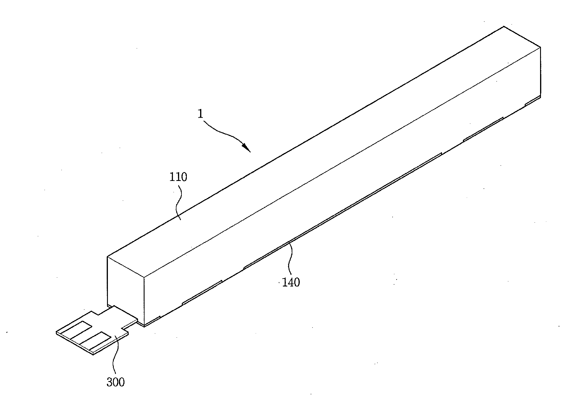
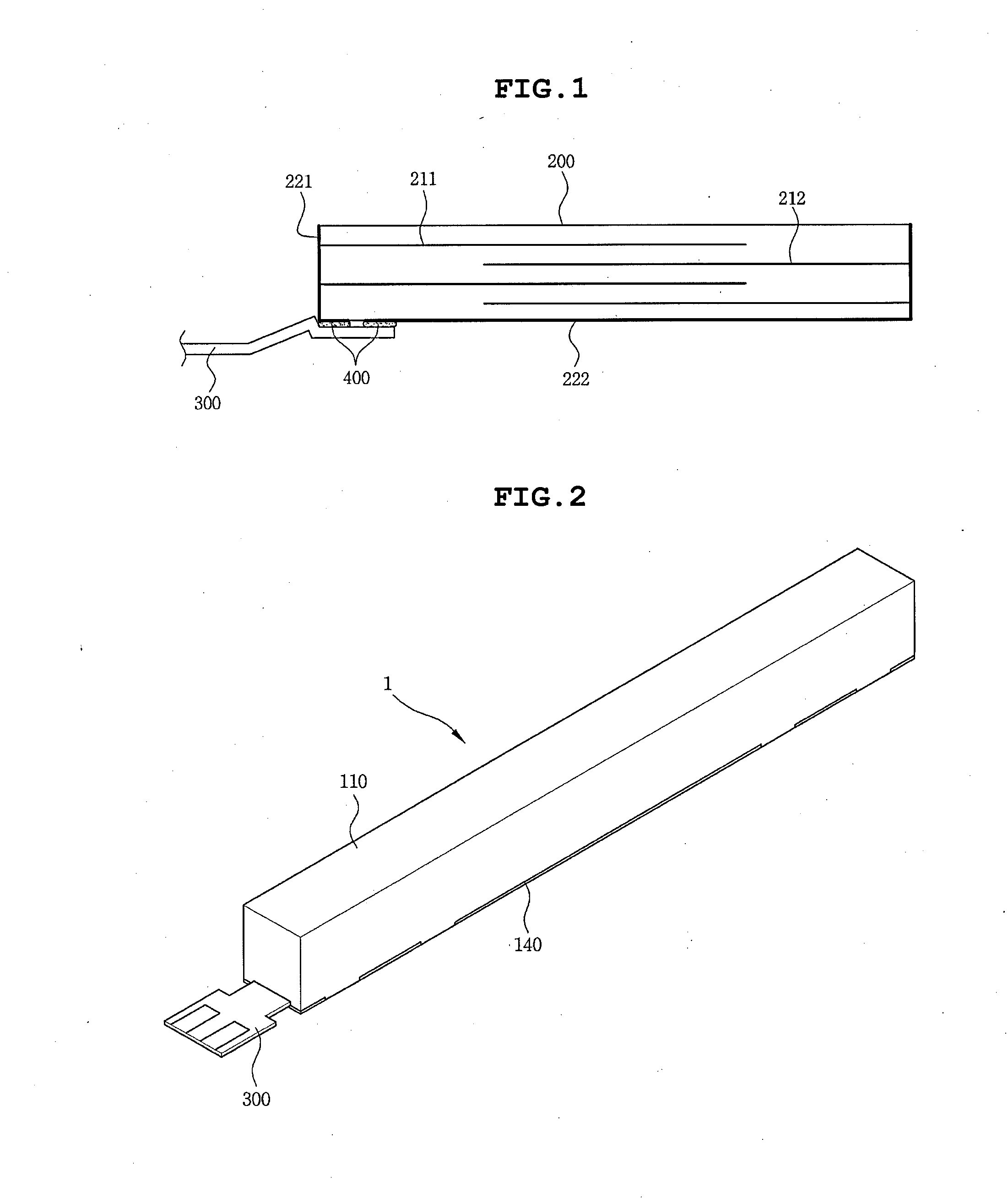
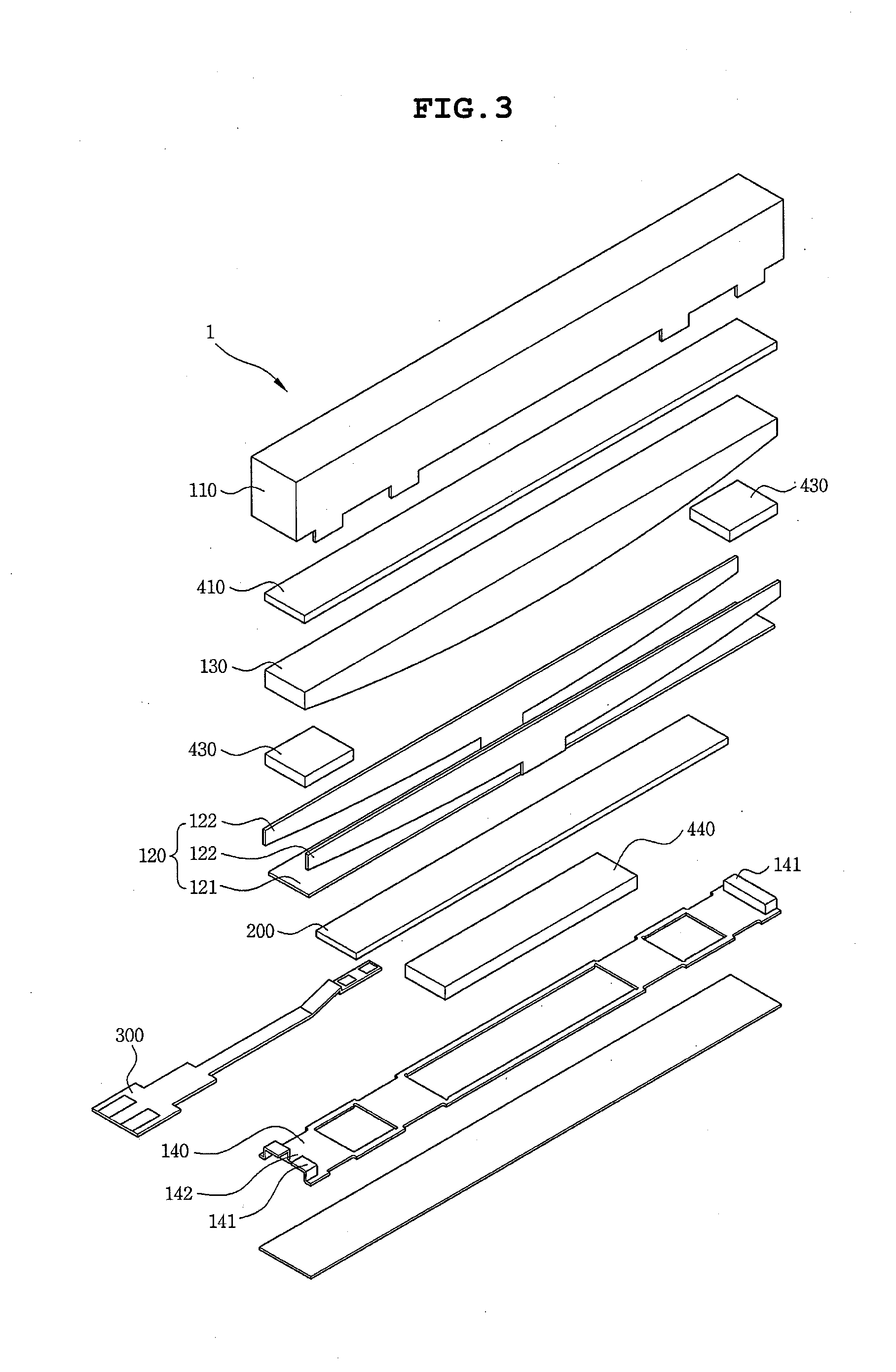
[0032]The objects, features and advantages of the present invention will be more clearly understood from the following detailed description of the preferred embodiments taken in conjunction with the accompanying drawings. Throughout the accompanying drawings, the same reference numerals are used to designate the same or similar components, and redundant descriptions thereof are omitted. Further, in the following description, the terms “first,”“second,”“one side,”“the other side” and the like are used to differentiate a certain component from other components, but the configuration of such components should not be construed to be limited by the terms. Further, in the description of the present invention, when it is determined that the detailed description of the prior art would obscure the gist of the present invention, the description thereof will be omitted.

[0033]Hereinafter, a piezo vibration module according to preferred embodiments of the present invention will be described in d...


PUM


Abstract

Disclosed herein is a piezo vibration module, including: a piezo element having a pattern of an internal electrode printed therein and having an external electrode connected to the internal electrode disposed on an outer surface thereof; a flexible printed circuit board (FPCB) having each terminal and applying power to the external electrodes of the piezo element; and a conductive adhesive interposed between the piezo element and the FPCB to electrically connect the piezo element to the flexible printed circuit board.

Description

CROSS REFERENCE TO RELATED APPLICATION[0001]This application claims the benefit of Korean Patent Application No. 10-2013-0034737, filed on Mar. 29, 2013, entitled “Piezo Vibration Module” which is hereby incorporated by reference in its entirety into this application.BACKGROUND OF THE INVENTION[0002]1. Technical Field[0003]The present invention relates to a piezo vibration module.[0004]2. Description of the Related Art[0005]Generally, in portable electronic devices, such as a portable phone, an E-book terminal, a game machine, a PMP, and the like, a vibration function has been variously utilized.[0006]In particular, a vibration generating apparatus for generating the vibration has been mainly mounted in the portable electronic device to be used as an alert function that is a silent receiving signal.[0007]With the multi-functionalization of the portable electronic device, a demand for small, integrated, and multi-functional vibration generating apparatus have increased.[0008]Further,...

Claims


Application Information

Patent Timeline
Patent Type & Authority Applications(United States)
IPC IPC(8): H01L41/053H01L41/04
CPCH01L41/053H01L41/042H01L41/0933B06B1/0603B06B1/0662H01L41/0475H10N30/875H10N30/88H10N30/2041H10N30/80
Inventor SON, YEON HOPARK, KYUNG SUJEONG, SEUNG HYEONCHOI, JOON
Owner MPLUS
Learn More