Reference Position Detection Device For Rotary Mechanism, Platen Gap Adjustment Mechanism, And Printer

a technology of reference position and adjustment mechanism, which is applied in the direction of measurement device, power drive mechanism, instrument, etc., can solve the problems of increasing the outside diameter of the reference position detection device, unable to make the device small and compact, and not being able to provide sufficient space for assembling the platen gap adjustment mechanism, etc., to achieve the effect of little space for movemen

Inactive Publication Date: 2014-10-02
SEIKO EPSON CORP
View PDF5 Cites 4 Cited by
  • Summary
  • Abstract
  • Description
  • Claims
  • Application Information

AI Technical Summary

Benefits of technology

[0011]A small, compactly configured reference position detection device according to the present invention for a rotary mechanism requires little space for movement of a detection flag around the rotary member.

Problems solved by technology

The required outside diameter of the reference position detection device therefore increases, and the device cannot be made small and compact.
Providing sufficient space sufficient to assemble a platen gap adjustment mechanism may therefore not be possible.

Method used


Image

  • Reference Position Detection Device For Rotary Mechanism, Platen Gap Adjustment Mechanism, And Printer
  • Reference Position Detection Device For Rotary Mechanism, Platen Gap Adjustment Mechanism, And Printer
  • Reference Position Detection Device For Rotary Mechanism, Platen Gap Adjustment Mechanism, And Printer

Examples


Embodiment Construction

[0049]A preferred embodiment of the present invention is described below with reference to the accompanying figures. The following embodiment describes the invention applied to detecting the reference position of a platen gap adjustment mechanism used in an inkjet printer with a reversing unit enabling two-sided printing. The invention can obviously also be used as a device for detecting the reference position of a rotary mechanism other than the platen gap adjustment mechanism of a printer.

General Configuration of a Printer

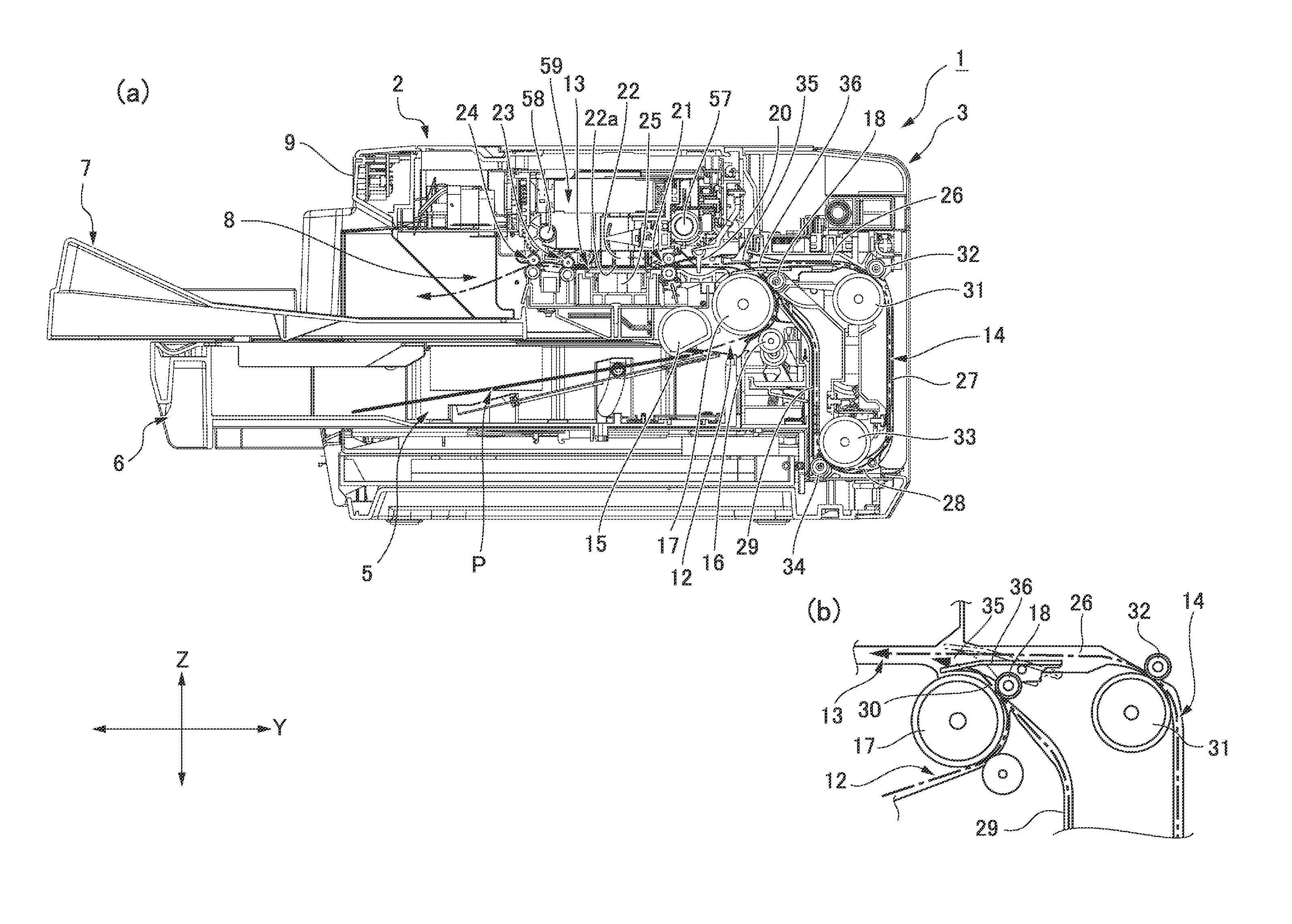
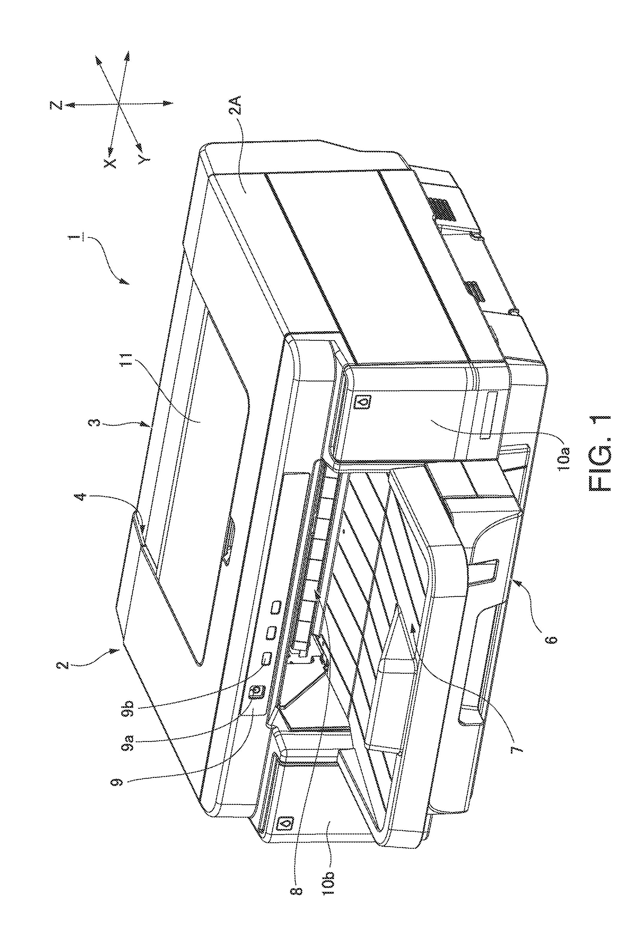
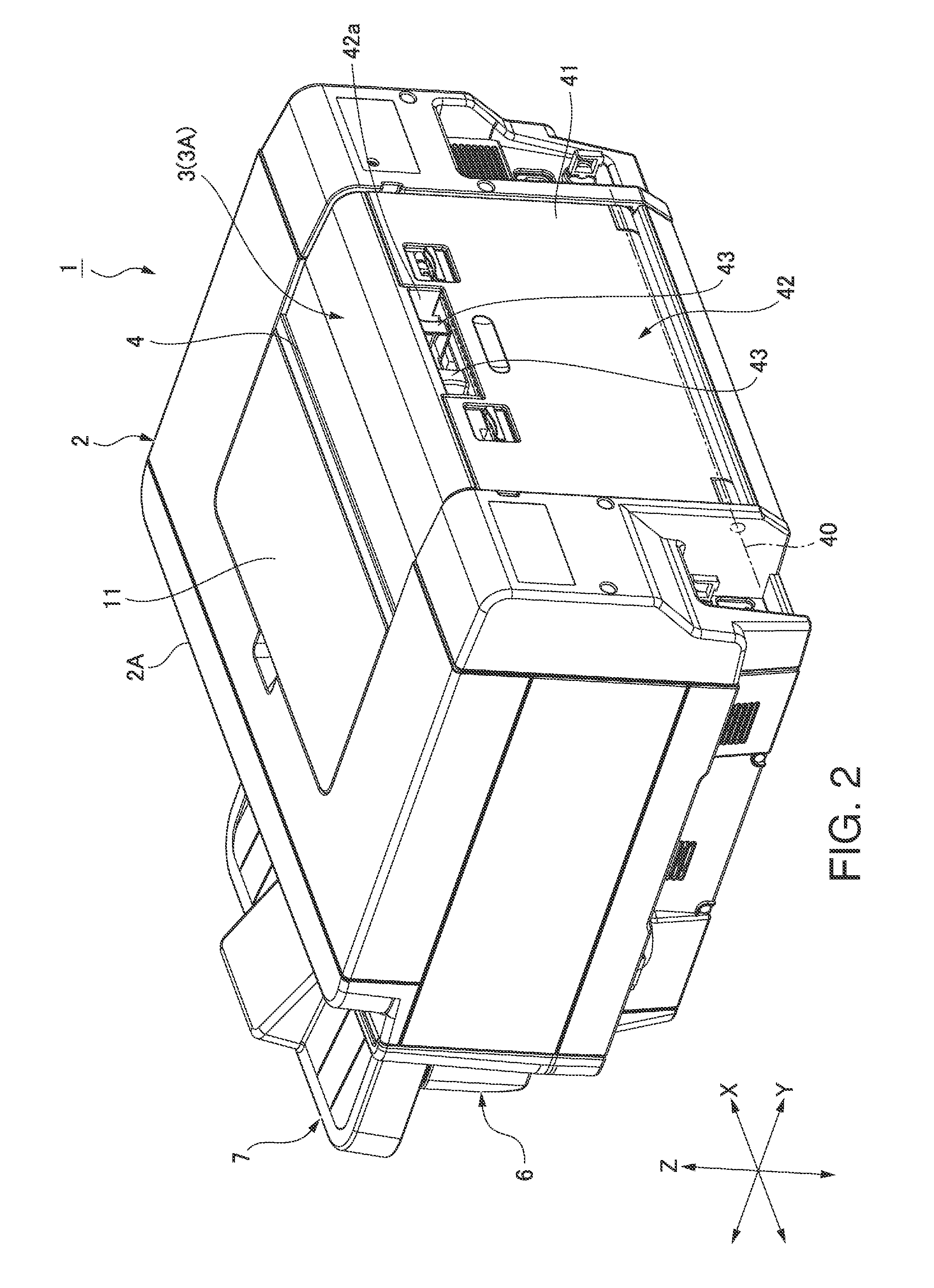
[0050]FIG. 1 is an external oblique view from the front of an inkjet printer (“printer” below) according to this embodiment of the invention, and FIG. 2 is an external oblique view of the printer from the back. FIG. 3 (a) is a vertical section view and FIG. 3 (b) is a partial section view of the internal configuration of the printer.

[0051]The general configuration of the printer 1 is described referring primarily to FIG. 1 and FIG. 2. The printer 1 has a printer ...


PUM


Abstract

A small, compactly configured reference position detection device 170 for a rotary transfer mechanism includes a rotary member 130 that can rotate through a rotational angle less than one revolution from a first rotational position past a second rotational position and reference position to a third rotational position; a detection flag disc 151 that can move in a range from a first position past a detection position to a second position; a detector 162 that detects the detection flag passing the detection position, and a flag moving mechanism. The flag moving mechanism can move the detection flag disc 151 tracking the rotary member 130. The position of detection flag disc 151 movement when passing the reference position of the rotary member 130 is the detection position.

Description

BACKGROUND[0001]1. Technical Field[0002]The present invention relates to a reference position detection device for a rotary mechanism that detects a rotational reference position within one revolution of a rotary member. A reference position detection device for a rotary mechanism of the invention can be used in a platen gap adjustment mechanism to adjust the gap between the printhead and platen in a printer.[0003]2. Related Art[0004]Printers such as inkjet printers commonly have a platen gap adjustment mechanism to adjust the gap between the nozzle face of the inkjet head and the platen, or the gap between the nozzle face and the printing surface of the print medium conveyed over the platen.[0005]JP-A-2005-280206 and JP-A-2005-280209 teach printers having this type of platen gap adjustment mechanism. A carriage carrying the printhead is supported by two carriage guide rails in these printers. The two carriage guide rails are attached to an elevator frame, and the elevator frame is ...

Claims


Application Information

Patent Timeline
Patent Type & Authority Applications(United States)
IPC IPC(8): G01B11/14B41J25/308
CPCB41J25/308G01B11/14
Inventor ARUGA, YUICHIIMAE, TOSHIHIRO
Owner SEIKO EPSON CORP
Why Eureka
Try Eureka