Object localization in X-ray images

a technology of object localization and x-ray images, which is applied in the field of object localization in x-ray images, can solve the problems of inability to show the position of all catheters in relation to each other or the detailed endocardial anatomy, in real time, and the complexity of ablation procedures is very time-consuming, and achieves small angular range, improved depth estimation accuracy, and convenient use.

Inactive Publication Date: 2013-01-08
KONINKLIJKE PHILIPS ELECTRONICS NV
View PDF10 Cites 0 Cited by
  • Summary
  • Abstract
  • Description
  • Claims
  • Application Information

AI Technical Summary

Benefits of technology

[0012]This makes it possible to obtain a depth estimate without using special localization hardware, because the x-ray system, which is already in use during an intervention, is used to obtain the depth estimate of the object. The system is convenient to use, because it does not involve large rotational movements of the gantry or time-consuming positioning procedures. An advantage is that it is no longer necessary to use an electromagnetic EP navigation system.
[0013]The x-ray images, by themselves, provide information about two dimensions of the position of the object. The third dimension, in particular along the axis intersecting the x-ray source and the middle of the detector plane, cannot normally be derived by inspecting the x-ray images. This third dimension is referred to as the depth of the object. The wiggling motion of the gantry causes the x-ray source and x-ray detector to wiggle, which provides views of slightly different perspectives. The slightly different perspectives may be used to estimate the depth parameter of the object. Because a plurality of images is acquired along the wiggling motion, the accuracy of the depth estimate is improved compared to stereo computations based on only two images. Moreover, the wiggling motion is not hindered by objects that may be positioned near the patient because the wiggling motion only spans a relatively small angular range.
[0014]The wiggling motion is usually limited to at most about 10 degrees, at maximum to about 15 degrees, which prevents the system to hinder most objects surrounding the patient. Another characteristic of the wiggling motion is that it may be a substantially periodic motion or even a fully periodic motion. The same trajectory may be repeated a number of times to improve the accuracy of the depth estimation. As long as the base of the cone is smooth (e.g., circular or elliptic), it is relatively easy to perform the wiggling motion repeatedly in a smooth movement, which leads to a more stable, reproducible movement.

Problems solved by technology

However, neither tool can show the position of all catheters in relation to each other or the detailed endocardial anatomy, in real time.
Due to the complexity of the anatomy and the lack of integrated tools, complex ablation procedures are very time-consuming and usually last several hours.

Method used


Image

  • Object localization in X-ray images
  • Object localization in X-ray images
  • Object localization in X-ray images

Examples


Embodiment Construction

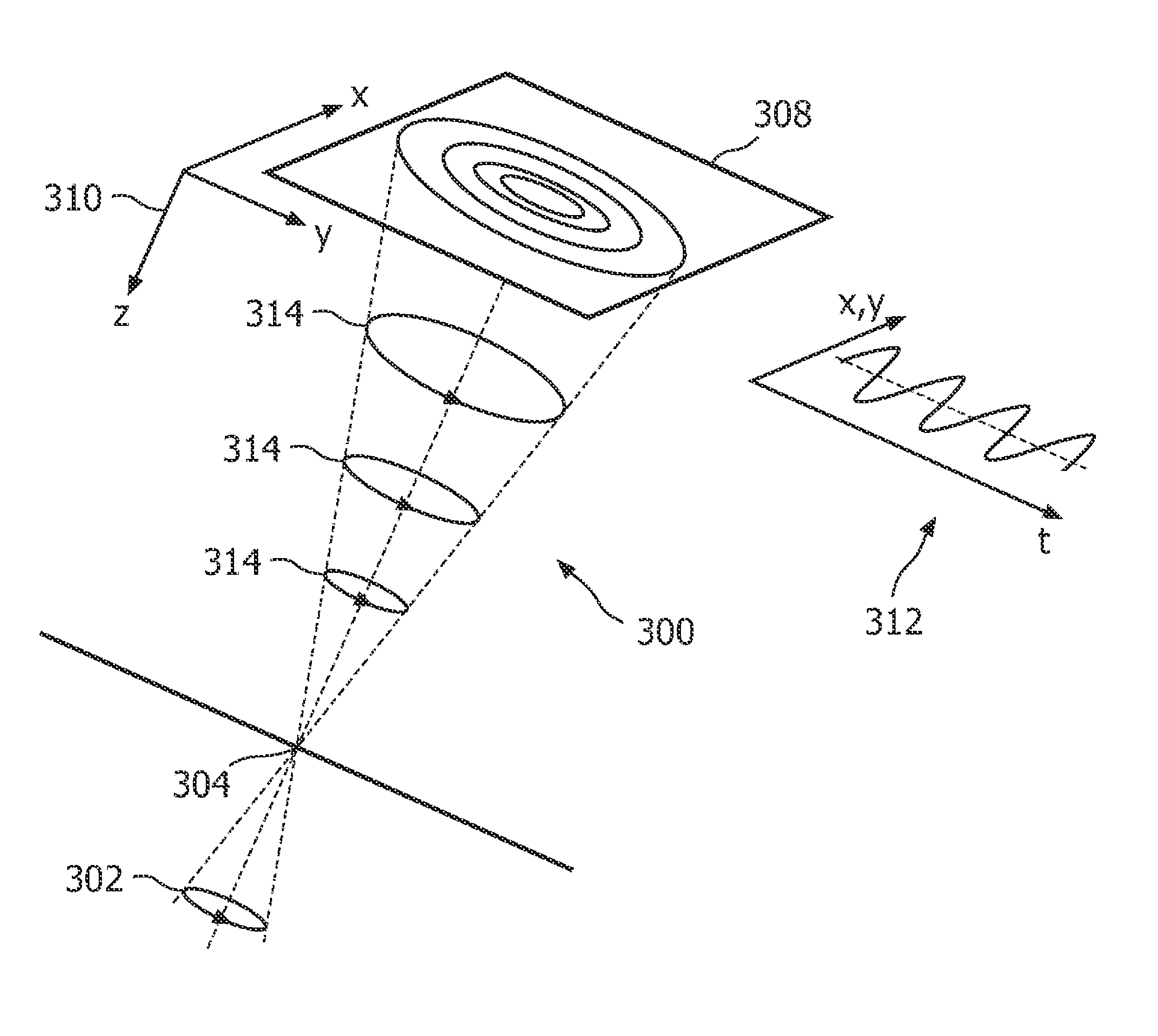
[0027]In this detailed description, several methods, systems, and computer program products are described that enable to estimate image depth information by use of conventional X-ray imaging. One of the applications discussed is three-dimensional (3D) position localization for electrophysiology (EP) procedures. However, the ideas and the embodiments described are applicable to a wide range of applications, in particular where automated object detection and tracking is feasible.

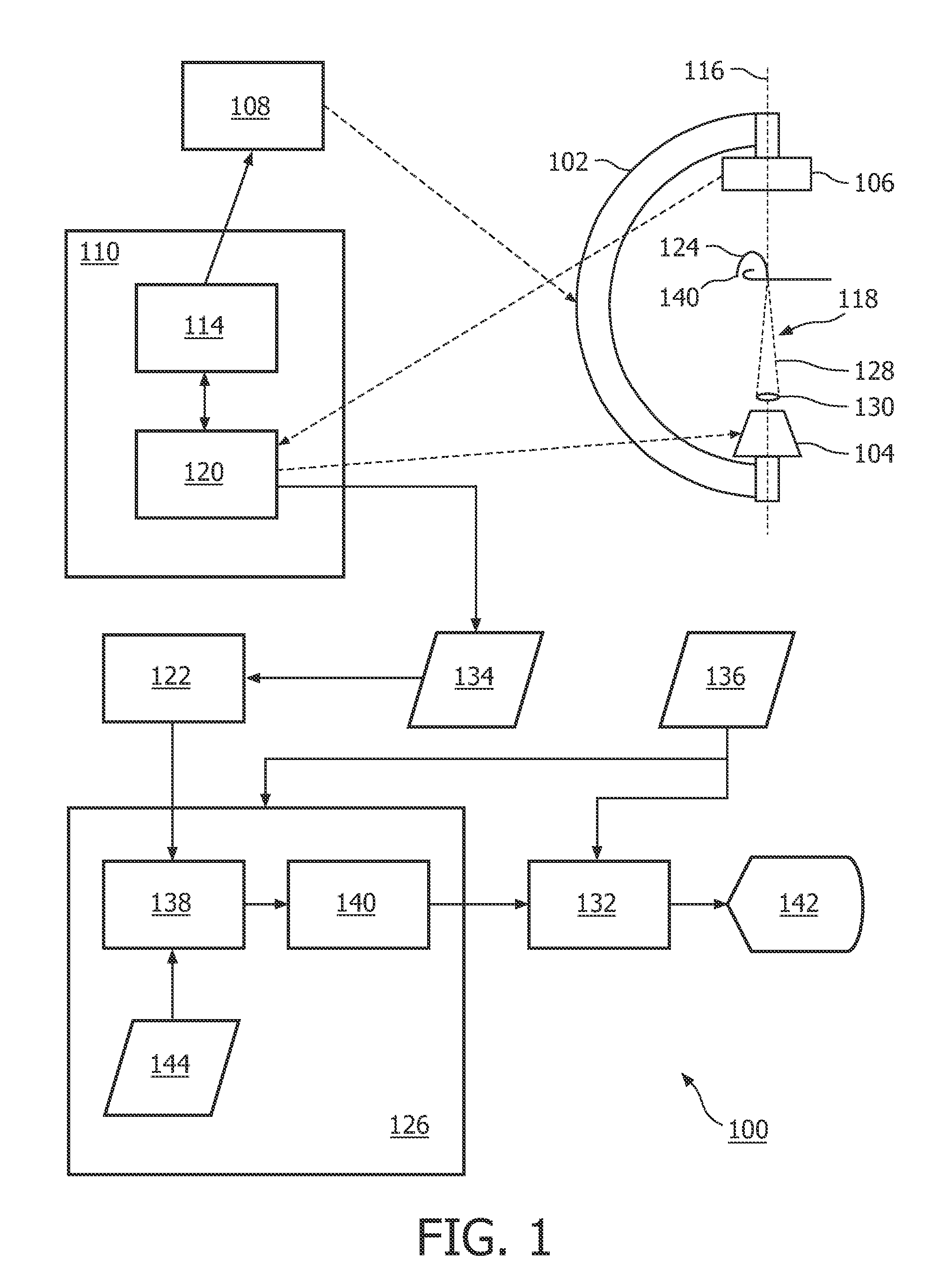
[0028]Such X-ray based 3D localization may be based on (ultra) low-dose fluoroscopy on monoplane geometry. Biplane and other geometries may also be used, although the information of only one detector is sufficient to provide depth information. The methods may be based in part on automated object tracking and / or signal processing, and on precession of the gantry on which the X-ray source and / or X-ray detector are mounted.

[0029]Fluoroscopy guided ablation focuses on guiding the physician through the position of ...


PUM


Abstract

An x-ray system (100) comprises a gantry (102) on which an x-ray source (104) and an x-ray detector (106) are mounted. A control unit (110) comprises means (114) for effectuating a wiggling motion of the gantry, wherein an axis (116) connecting the x-ray source and the x-ray detector traces a surface (128) of a cone (118). The x-ray source and the x-ray detector have a fixed position with respect to the axis. The control unit comprises means (120) for acquiring a series of x-ray images during the wiggling motion of the gantry. An object recognition unit (122) detects an object (124) appearing in the series of x-ray images to obtain a tracked path. A depth estimation unit (126) uses the tracked path for estimating a depth parameter indicative of a position of the object in a direction substantially parallel to the axis (116).

Description

FIELD OF THE INVENTION[0001]The invention relates to object localization in x-ray images.BACKGROUND OF THE INVENTION[0002]X-ray fluoroscopy is often used for guiding electrophysiology (EP) ablation procedures. It shows the position of all catheters in real-time. 3D mapping has greatly helped the development of complex ablation procedures by showing the position of the catheter in relation to a 3D representation of the cardiac contours. However, neither tool can show the position of all catheters in relation to each other or the detailed endocardial anatomy, in real time.[0003]The EP Navigator, which is available from Philips Healthcare, is able to confirm the position of a catheter or lead position with respect to a 2D projection of a detailed 3D cardiac anatomy in the EP intervention lab. This information can help a physician to carry out complex EP procedures with greater confidence, in a more intuitive way. Such tools may provide an automatically segmented 3D CT image. This image...

Claims


Application Information

Patent Timeline
Patent Type & Authority Patents(United States)
IPC IPC(8): H05G1/02
CPCA61B6/12A61B6/4447A61B6/588G06T7/0046G06T7/0065A61B19/5244A61B6/027G06T2207/10081G06T2207/10116G06T2207/30021G06T2207/30048A61B34/20G06T7/75G06T7/55
Inventor NIJHOF, NIELSSTEGEHUIS, HERMAN
Owner KONINKLIJKE PHILIPS ELECTRONICS NV
Why Eureka
Try Eureka