Method and driving assembly for operating a weaving machine

A technology for driving devices and looms, which is applied in looms, textiles, papermaking, textiles, etc., can solve the problems of increasing the cost of driving devices, and achieve the effect of favorable cost and small structural size

Inactive Publication Date: 2011-06-08
LINDAUER DORNIER GMBH
View PDF2 Cites 0 Cited by
  • Summary
  • Abstract
  • Description
  • Claims
  • Application Information

AI Technical Summary

Problems solved by technology

In particular, the separate drive of the additional flywheel mass with the associated high-power electronics increases the outlay for this type of drive

Method used


Image

  • Method and driving assembly for operating a weaving machine
  • Method and driving assembly for operating a weaving machine
  • Method and driving assembly for operating a weaving machine

Examples


Embodiment Construction

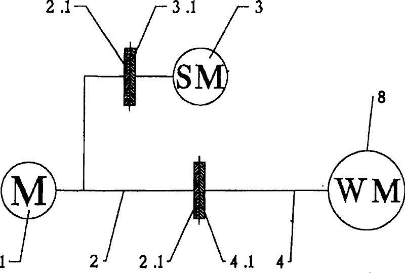
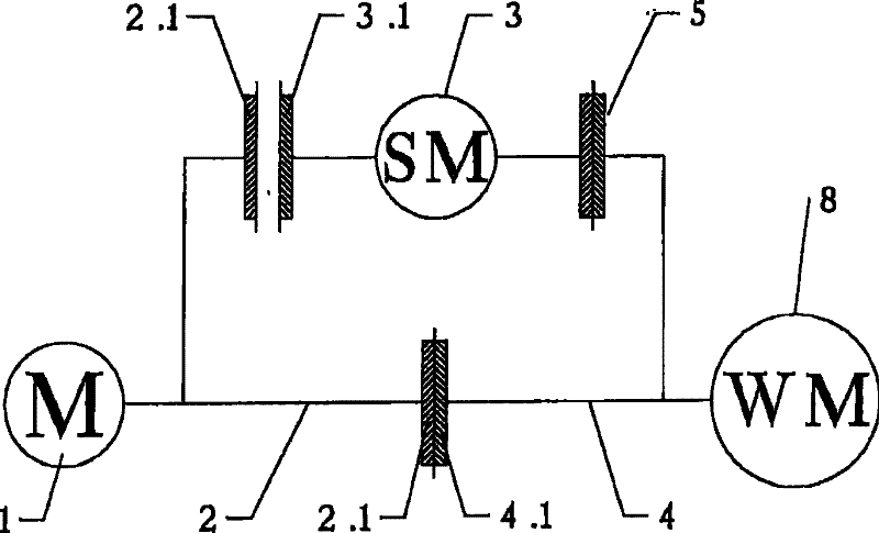
[0056] exist figure 1 The drive shown schematically in FIG. 1 shows a main motor 1 with its rotor shaft 2 and two clutch devices 2.1 secured to the rotor shaft in a non-rotatable manner. A clutch device 2.1 is switchably connected to a first output element 3.1, which is connected to the additional flywheel mass 3 in a non-rotatable manner.

[0057] The other clutch device 2.1 is shiftably connected to a second output element 4.1, which is connected to the main drive shaft 4 in a non-rotatable manner. The main drive shaft 4 drives the individual functional components of the weaving machine 8, such as, for example, weft insertion elements, shed forming devices and reeds.

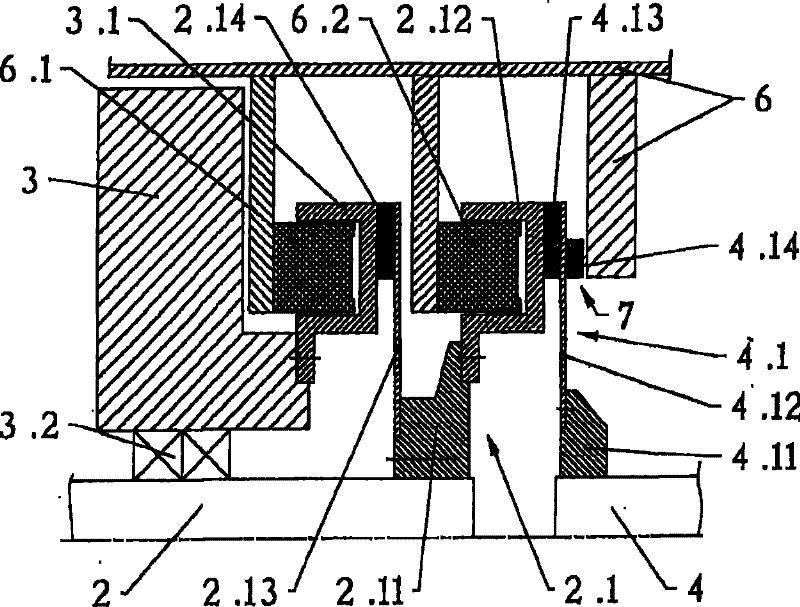
[0058] figure 2 The drive shown shows the rotor shaft 2 of the main motor 1 (not shown) and a clutch device 2 . The clutch device 2.1 comprises a clutch hub 2.11, a first clutch disc 2.12 rigidly connected thereto, and a second diaphragm spring 2.13 with a friction lining 2.14, which is connected to the cl...


PUM


Abstract

Disclosed is a weaving machine comprising a main motor, a main drive shaft for the weaving machine, which can be effectively connected to the main motor via a first shiftable coupling and can be driven by the main motor, and an additional rotating mass that can be effectively connected to the main motor via a second shiftable coupling and can be driven by the main motor. Only the additional rotating mass is initially accelerated to a nominal operating speed by the main motor that is effectively connected thereto, whereupon the effective connection between the main motor and the additional rotating mass is interrupted and the main motor is decelerated to a standstill. The main motor is then effectively connected to the main drive shaft, and the weaving machine is accelerated to the nominaloperating speed via the main drive shaft.; The previously accelerated additional rotating mass is effectively connected to the other driving elements once the weaving machine has been accelerated.

Description

technical field [0001] The invention relates to a method for operating a weaving machine and a drive for carrying out the method. Background technique [0002] An additional flywheel mass is used in the drive of the weaving machine in order to keep the nominal or operating speed as constant as possible. The moment of inertia effective at the main drive shaft of the loom varies during a weaving cycle and thus results in alternating torques and further alternating rotational speeds. Alternating rotational speeds are of course undesirable from a weaving point of view and should therefore be balanced. One such balance can be achieved most efficiently with a mechanical flywheel mass. [0003] During the start-up of the loom, however, the loom must be accelerated within a limited angular range at least to an operating nominal rotational speed, so that no slipping points occur in the fabric, for example, during the first reeding. [0004] Acceleration of a weaving machine with f...

Claims


Application Information

Patent Timeline
Patent Type & Authority Patents(China)
IPC IPC(8): D03D51/02D03D51/12
CPCD03D51/02D03D51/12
Inventor O・弗里德T・劳坎普J・霍茨
Owner LINDAUER DORNIER GMBH
Why Eureka
Try Eureka