Recording apparatus

Active Publication Date: 2014-10-02
SEIKO EPSON CORP
View PDF5 Cites 5 Cited by
  • Summary
  • Abstract
  • Description
  • Claims
  • Application Information

AI Technical Summary

Benefits of technology

[0040]According to the aspect, since the unit body that is attachable and detachable with respect to the recording apparatus main body is configured to have the first and the second rollers, when the unit b

Problems solved by technology

Accordingly, in this configuration, there is a problem in that when the apparatus is designed on the basis that paper of a large size is used, it is necessary to make the inversion roller large, and the size of the apparatus becomes large.
However, in this case, there is a problem in that the number of the disposed transportation rollers is likely to increase, and the number of components increases.
However, in this configuration, there is a problem in t

Method used


Image

  • Recording apparatus
  • Recording apparatus
  • Recording apparatus

Examples


first embodiment

Configuration of Transportation Section

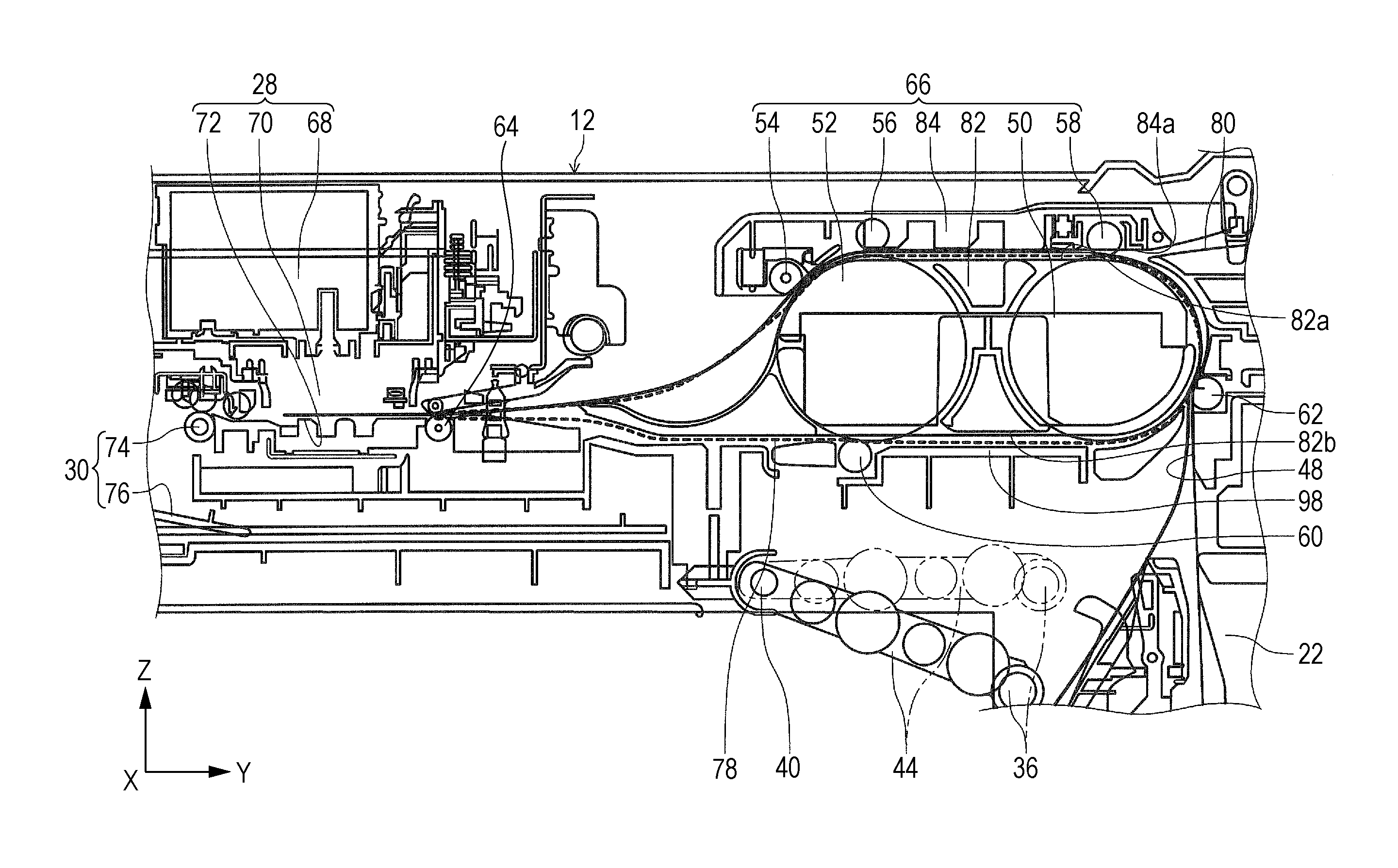
[0083]Subsequently, the transportation section 26 will be described with reference to FIGS. 3 and 5. In FIG. 5, a solid line indicates the transportation path of the medium fed from the medium container 20, and a broken line indicates the inverted path of the paper P. The first roller 50 and the second roller 52 are provided at the same position in the Z axis direction in FIG. 3. For this reason, it is possible to limit dimensions of disposition regions of the first roller 50 and the second roller 52 to the minimum in the Z axis direction.

[0084]The first roller 50 and the second roller 52 are disposed with a gap in the Y axis direction therebetween. That is, in the transportation path of the paper P, the first roller 50 is positioned on an upstream side of the transportation path, and the second roller 52 is positioned on the downstream side of the transportation path. The gap is set to have a length less than the minimum length in a transporta...

modification example of first embodiment

[0157](1) In the configuration of the embodiment, one each of the first roller 50 and the second roller 52 are provided at the center in a direction that intersects with the transportation direction of the paper P, that is, in the width direction of the unit main body 82 of the transportation unit 66. However, the embodiment may have a configuration in which at least any one of the first roller 50 and the second roller 52 is provided at multiple positions along the direction that intersects with the transportation direction of the paper P, that is, along the width direction of the unit main body 82. In particular, in a configuration in which the plurality of second rollers 52 are provided in the width direction, since the paper P is in contact with the second roller 52 at multiple positions in the width direction of the paper P and thus, it is possible to suppress oblique feeding of the paper P during the transportation thereof.

[0158](2) In a configuration in which at least any one ...

second embodiment

[0161]FIGS. 14 and 15 illustrate a printer 120 according to a second embodiment of the invention. The printer 120 is different from that of the first embodiment in that the first transportation driven roller 54, the second transportation driven roller 56 and the third transportation driven roller 58 are not provided on a transportation unit 122 but on an apparatus main body 124.

[0162]As illustrated in FIGS. 14 and 15, the printer 120 is configured in such a manner that the transportation unit 122 is attachable and detachable with respect to the apparatus main body 124. The back surface cover 22 is open and closed, and the transportation unit 122 is attached and detached with respect to the apparatus main body 124. Similarly to in the first embodiment, the transportation unit 122 is provided with the first roller 50 and the second roller 52. Similarly to in the first embodiment, when the transportation unit 122 is mounted onto the apparatus main body 124, and the drive transmission u...


PUM

PropertyMeasurementUnit
Forceaaaaaaaaaa
Diameteraaaaaaaaaa
Widthaaaaaaaaaa

Abstract

A recording apparatus includes a recording head that performs recording on a medium; a first roller that inverts the medium which is fed from a side of the recording head; and a second roller of which an outer circumferential surface is in contact with medium transportation paths before and after the medium is inverted by the first roller and which exerts a transportation force on the medium.

Description

BACKGROUND[0001]1. Technical Field[0002]The present invention relates to a recording apparatus that is represented by a facsimile, a printer or the like.[0003]2. Related Art[0004]In a recording apparatus that is represented by a facsimile, a printer or the like, there is also the recording apparatus that can perform recording on both surfaces of recording paper as an example of a medium. For example, as illustrated in JP-A-2012-240813, the recording apparatus has an inverted path in which the recording paper is inverted. The recording apparatus performs recording on a first surface (a front surface) of the recording paper, feeds the recording paper backward to the inverted path, and transports the recording paper again to a region that faces a recording head while a second surface (a back surface) thereof faces upward.[0005]In the recording apparatus according to JP-A-2012-240813, an outer circumferential surface of one roller (hereinafter, referred to as “inversion roller”) is used...

Claims


Application Information

Patent Timeline
IPC IPC(8): B41J11/04
CPCB41J11/04B41J3/60B65H85/00B65H2301/33214B65H2301/333B65H2801/06
Inventor OHASHI, KAZUYOSHINAKAHATA, AKINOBU
Owner SEIKO EPSON CORP
Why Eureka
Try Eureka