
Tool holder attaching/detaching structure of machine tool

a tool holder and machine tool technology, applied in the field of tool holder attachment/detachment structure of machine tool, can solve the problems of a considerable weight the burden of the worker's support and the fastening and so on of the fixing bolt while the worker supports the tool holder, so as to achieve easy and sure attachment/detachment work of the tool holder

Inactive Publication Date: 2014-10-02
DMG MORI SEIKI CO LTD
View PDF9 Cites 1 Cited by
  • Summary
  • Abstract
  • Description
  • Claims
  • Application Information

AI Technical Summary

Benefits of technology

The present invention provides a tool holder attaching / detaching structure of a machine tool that allows for easy and secure attachment / detachment of a tool holder. The structure includes a rotating member and a clamping member that work together to secure the tool holder to the base member. The attachment is quick and simple, reducing the workload and trouble of the operator. The rotating member and clamping member have matching depressions that make it easy to align and clamp the tool holder to the base member. The depressions of the rotating member and clamping member are tapered grooves, making it easy to align the tool holder with the wide depressions of the rotating member. A seating detection mechanism is also included to ensure that the tool holder is normally seated and to prevent clamping when the seating state is not normal.

Problems solved by technology

Having the many cutting tools, the tool holder has a considerable weight.
Therefore, the aforesaid work of the fastening and so on of the fixing bolt while supporting the tool holder by the worker is a considerable burden for the worker.

Method used


Image

  • Tool holder attaching/detaching structure of machine tool
  • Tool holder attaching/detaching structure of machine tool
  • Tool holder attaching/detaching structure of machine tool

Examples


Embodiment Construction

[0036]Hereinafter, an embodiment of the present invention will be described based on the attached drawings.

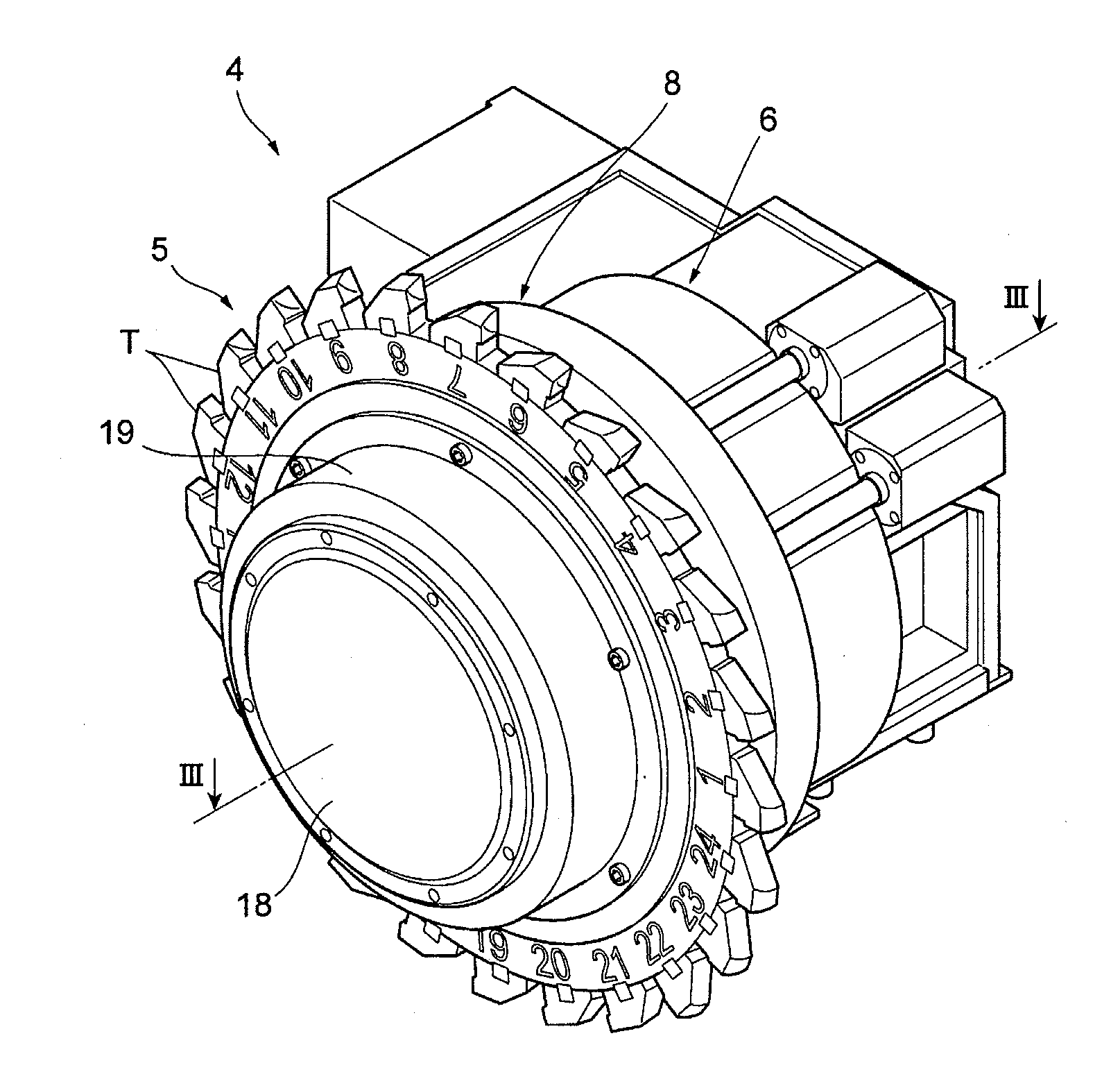
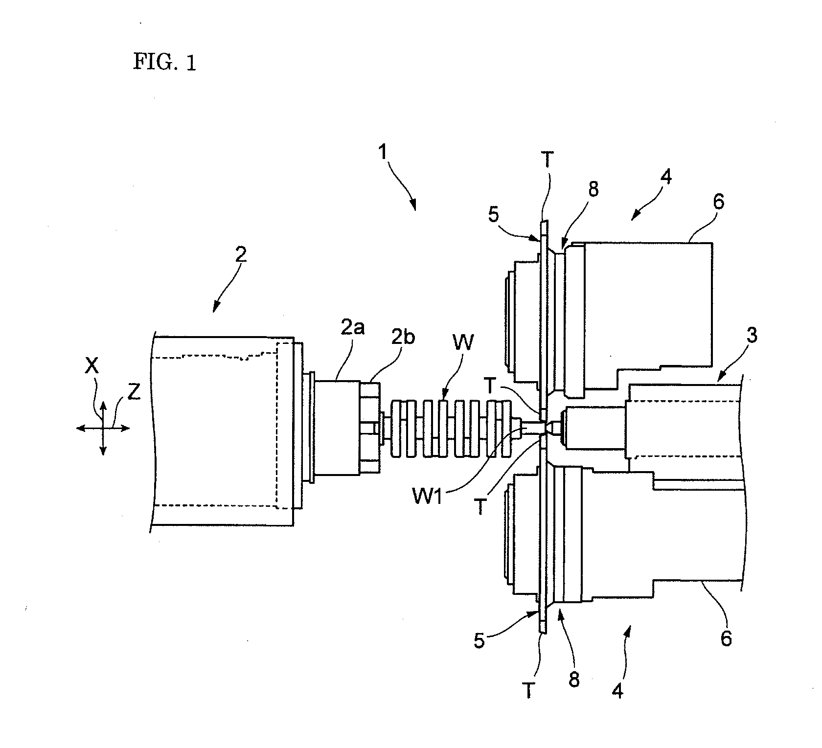
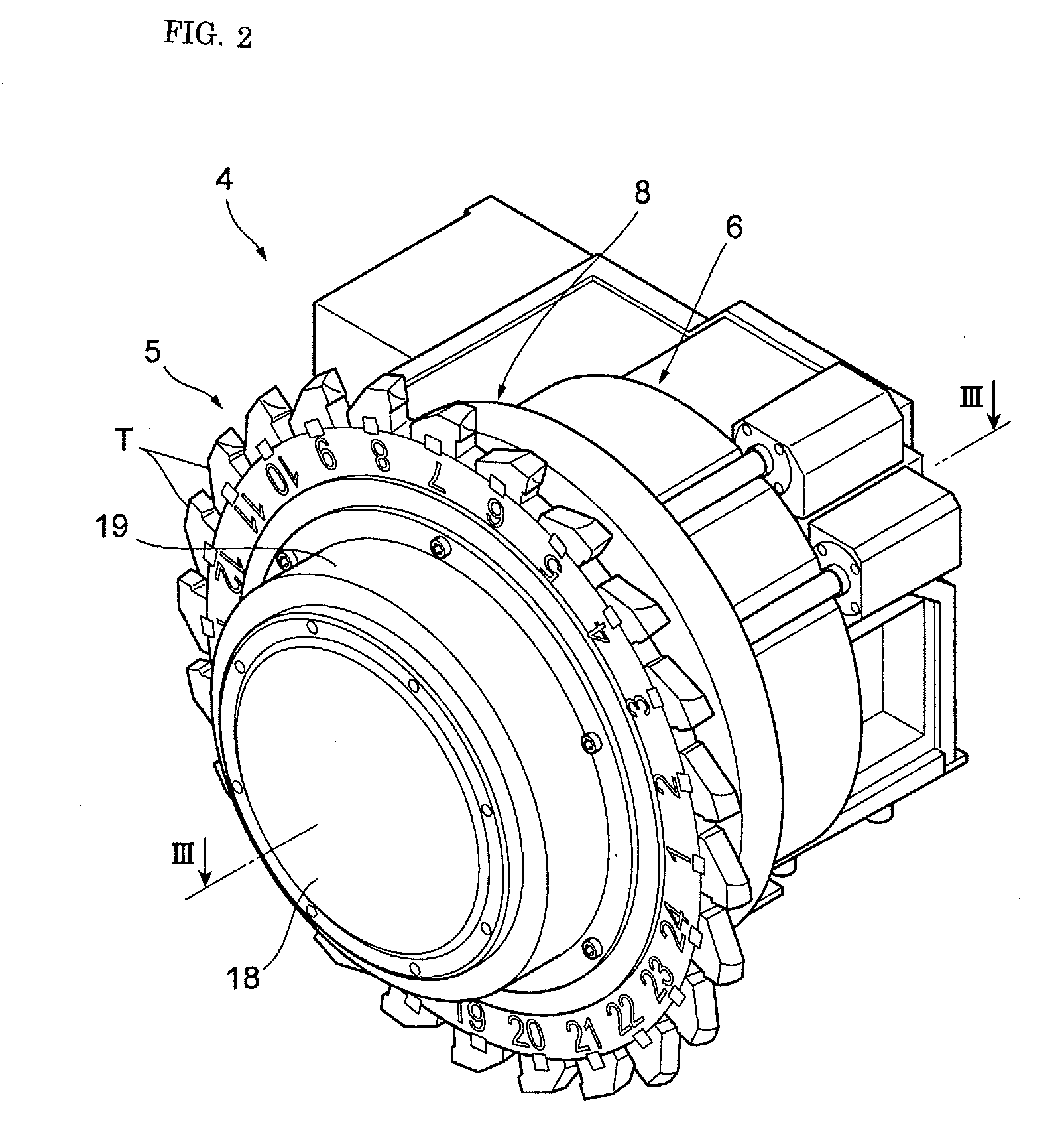
[0037]FIG. 1 to FIG. 11D are explanatory views of a tool holder attaching / detaching structure of a machine tool according to an embodiment 1 of the present invention.

[0038]In the drawings, 1 denotes the machine tool including the tool holder attaching / detaching structure of this embodiment. The machine tool 1 includes: a spindle headstock 2 disposed on a not-shown bed; a tailstock 3 coaxial with the spindle headstock 2 and disposed to be movable in its axial (Z-axis) direction; and tool posts 4, 4 disposed on both sides of the Z axis to be movable in the Z-axis direction and in an X-axis direction perpendicular to the Z-axis.

[0039]In the machine tool 1, one end of a workpiece W such as a crankshaft is grasped by a chuck 2b mounted on a spindle 2a of the spindle headstock 2, the other end is supported by the tailstock 3, and cutting edges of cutting tools T fixed to tool holders...


PUM

PropertyMeasurementUnit
Pressureaaaaaaaaaa

Abstract

In a case where a tool holder 5 having a plurality of cutting tools T are attachably / detachably mounted on a base member 8, the tool holder 5 is formed in a ring shape and has depressions 5a and projections 5b on an inner periphery, and by aligning the depressions and projections 5a, 5b of the tool holder 5 with projections 9b and depressions 9a formed on an outer periphery of a rotating member 9 rotatably mounted on the base member 8, the tool holder 5 is mountable to or removal from the base member 8. The tool holder 5 is clamped to the base member 8 by being pressed against a seating surface 8e of the base member 8.

Description

BACKGROUND OF THE INVENTION[0001]1. Field of the Invention[0002]The present invention relates to a tool holder attaching / detaching structure of a machine tool in which a tool holder including a plurality of cutting tools is attachably / detachably mounted on a base member such as a rotary indexing shaft.[0003]2. Description of the Related Art[0004]There is a machine tool including a tool holder to whose outer periphery a plurality of cutting tools are attached (for example, refer to Japanese Translation of PCT International Application Publication No. 2010-521328).[0005]In the machine tool of this type, in order to perform changing, repairing, and so on of the cutting tools, it is necessary for the tool holder to be detachable from a base member of the machine. A conceivable structure making the tool holder attachable / detachable is a structure in which the tool holder is fixed to the base member by bolting. In the case of this structure, in order to perform an attaching / detaching work...

Claims


Application Information

Patent Timeline
IPC IPC(8): B23C5/00
CPCB23C2210/24B23C5/006B23Q3/12B23B29/242B23B31/113B23B31/4073B23B2270/025Y10T407/1934Y10T409/309408B23B31/30
Inventor UEDA, TOSHIOSUZUKI, YUMIYAMADA, SOICHIRO
Owner DMG MORI SEIKI CO LTD
Learn More