System and a method for designing high degree of freedom (DOF) compliant nanopositioners

a nanopositioner and high degree of freedom technology, applied in the field of micro electro mechanical systems, can solve the problems of reducing system efficiency, reducing system efficiency, and reducing the efficiency of the system, so as to increase the output displacement, reduce the flexural and reduce the axial stiffness of the box spring

Inactive Publication Date: 2014-10-09
POURZAND HOORAD +2
View PDF0 Cites 1 Cited by
  • Summary
  • Abstract
  • Description
  • Claims
  • Application Information

AI Technical Summary

Benefits of technology

[0026]According to one embodiment herein, an axial stiffness of the box spring is increased to increase an output displacement of the primary long beam of the nano-positioners. The output displacement is a lateral displacement or a rotational displacement or a combination of both.
[0027]According to one embodiment herein, a flexural stiffness of the box spring is reduced to increase an output displacement of the primary long beam of the nano-positioners. The output displacement is a lateral displacement or a rotational displacement or a combination of both.
[0028]According to one embodiment herein, the primary long beam further comprises a serpentine shaped spring to increase an in-plane rigidity of the nano-positioner.

Problems solved by technology

However the existing prior art methods fail to provide a lateral, axial and rotational movement through the same set of microactuators.
But the system becomes bulky and complicated as the system assembly has a high number of microactuators.
Further a particular number of microactuators remain resistive while performing a movement thereby reducing the efficiency of the system.

Method used


Image

  • System and a method for designing high degree of freedom (DOF) compliant nanopositioners
  • System and a method for designing high degree of freedom (DOF) compliant nanopositioners
  • System and a method for designing high degree of freedom (DOF) compliant nanopositioners

Examples


Embodiment Construction

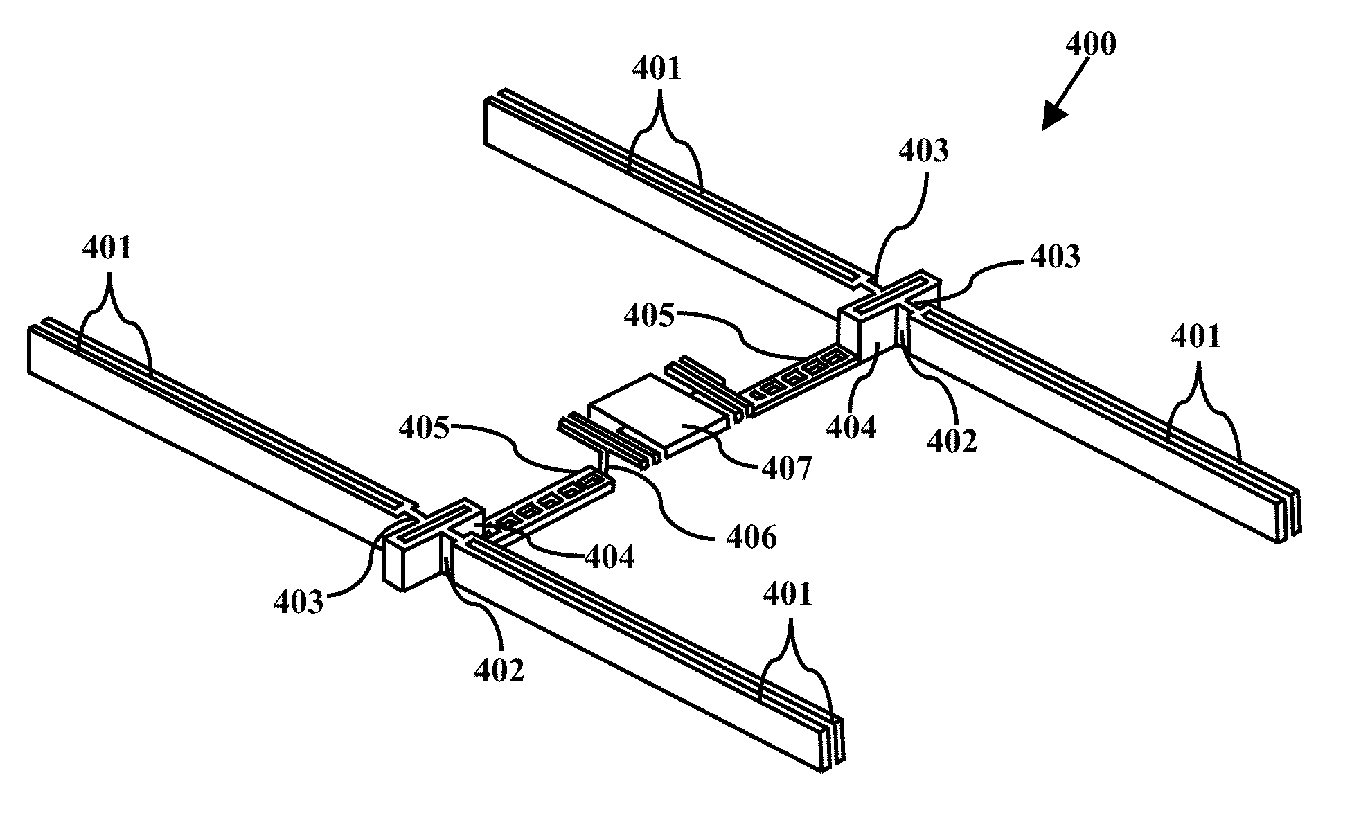
[0012]The primary object of the embodiment herein is to provide a nano-positioner with high degree of freedom (DOF) and a method for designing a high degree of freedom (DOF) nano-positioner using at-least a 2-DOF micromanipulator.

[0013]Another object of the embodiments herein is to provide a nano positioned system and method for facilitating a lateral, an axial and a rotational movement using a same set of micro actuators.

[0014]Yet another object of the embodiments herein is to provide a nano-positioner system for facilitating a high displacement while performing a lateral, an axial and a rotational movement.

[0015]Yet another object of the embodiments herein is to provide a nano-positioner system for providing a symmetrical buckling effect while performing a lateral, an axial and a rotational movement.

[0016]Yet another object of the embodiments herein is to provide a nano-positioner system for providing an in plane and an out-of-plane movement.

[0017]Yet another object of the embodim...


PUM

PropertyMeasurementUnit
degrees of freedomaaaaaaaaaa
degree of freedomaaaaaaaaaa

Abstract

The embodiments herein disclose a high degree of freedom (DOF) compliant nano-positioners and a method to fabricate the high DOF compliant nano-positioners. The system comprising a central stage and a plurality of micromanipulators is connected to the central stage. Each of the plurality of micromanipulators comprises a micro-actuator, a primary long beam and a primary micro beam. The micro-actuator comprises a pair of conducting pads, a secondary micro-beam, a secondary long beam and a box spring. A preset amount of the non-zero voltage is applied on the conducting pads to cause a displacement in the micromanipulator. The embodiments herein also disclose a fabrication method of developing a bi-planar structure for a high degree of freedom nano-positioner.

Description

CROSS-REFERENCE TO RELATED APPLICATIONS[0001]This application claims priority under 35 U.S.C. .sctn.119 (e) to U.S. Provisional Application No. 61 / 621,517 filed on Apr. 8, 2012, which is hereby incorporated by reference.BACKGROUND[0002]1. Technical Field[0003]The embodiments herein generally relate to a micro electro mechanical systems with thermal micro actuators and particularly relate to a system and a method for generating a movement of nanoscale using thermal micro-actuators. The embodiments herein more particularly relate to a nano-positioner with high degree of freedom (DOF) and a method for fabricating a high DOF nano-positioner.[0004]2. Description of Related Art[0005]A microactuator is a microscopic servomechanism that circulates a measured amount of energy to supports a movement of a plurality of mechanisms connected with the microactuator. Also the microactuators convert energy into a mechanical work at the micro scale.[0006]A thermal microactuator utilizes a property of...

Claims


Application Information

Patent Timeline
Patent Type & Authority Applications(United States)
IPC IPC(8): F03G7/06
CPCF03G7/06Y10T29/49229
Inventor POURZAND, HOORADALASTY, ARIAGHAEMI, REZA
Owner POURZAND HOORAD
Why Eureka
Try Eureka