Electro-optic current sensor with high dynamic range and accuracy

a technology of optical current and dynamic range, applied in the field of optical current sensors, can solve the problems of increasing complexity and cost, affecting the accuracy of the current sensor, and reducing the effect of extraneous electromagnetic interference, and low verdet constan

Active Publication Date: 2014-10-09
MICATU
View PDF3 Cites 6 Cited by
  • Summary
  • Abstract
  • Description
  • Claims
  • Application Information

AI Technical Summary

Benefits of technology

[0018]A further aspect of the present disclosure relates to an electro-optic current sensor with a polarizing beam splitter having a low Verdet constant. The sensor material has a high Verdet constant and is positioned very close to the polarizing beam splitter. The material composition and spatial arrangement of the PBS relative to the sensor mat...

Problems solved by technology

Hence they are expensive and cumbersome to install.
It is, however, difficult to make use of the current sensor disclosed.
This adds to the complexity and the cost.
However, the prior art does not teach an economica...

Method used


Image

  • Electro-optic current sensor with high dynamic range and accuracy
  • Electro-optic current sensor with high dynamic range and accuracy
  • Electro-optic current sensor with high dynamic range and accuracy

Examples


Embodiment Construction

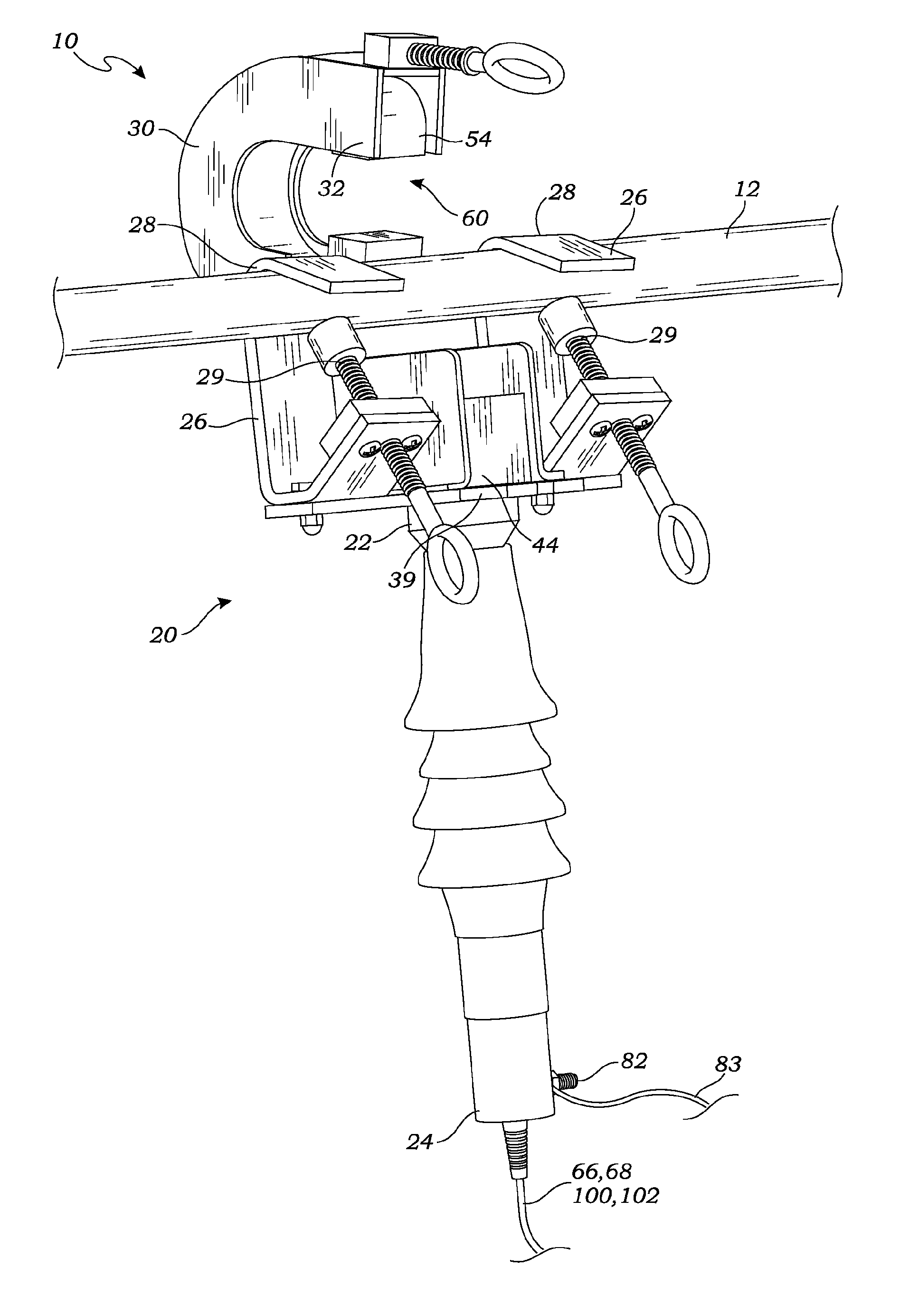
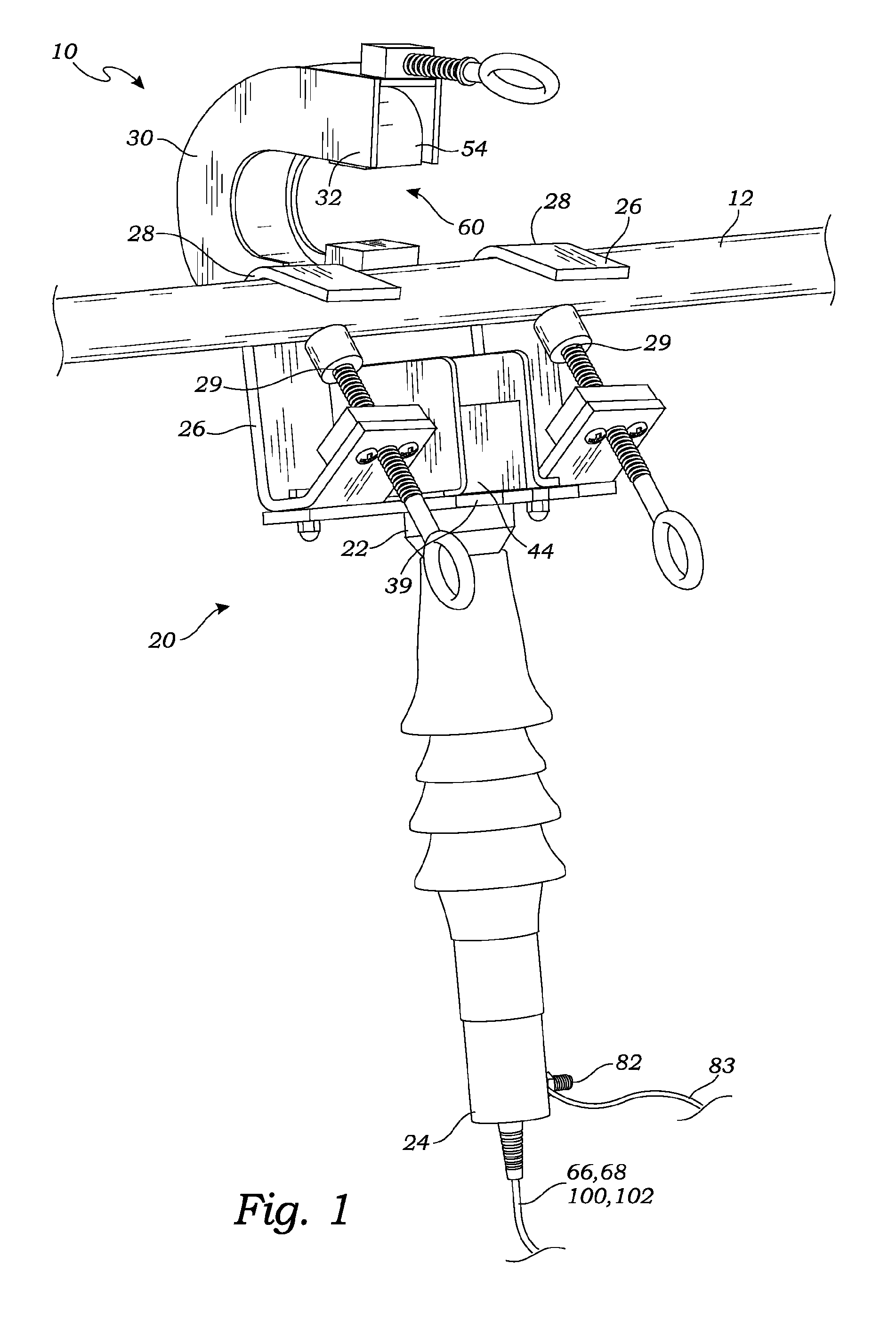
[0051]FIG. 1 is a perspective view of one embodiment of the optical sensor assembly 10 wherein the magnetic concentrator 54 is in the open position and has not yet been placed in a position to encompass or partially encompass the current carrying cable. It is noted, nevertheless, that in this position, the current carrying cable 12 is firmly held by the optical sensor assembly 10.

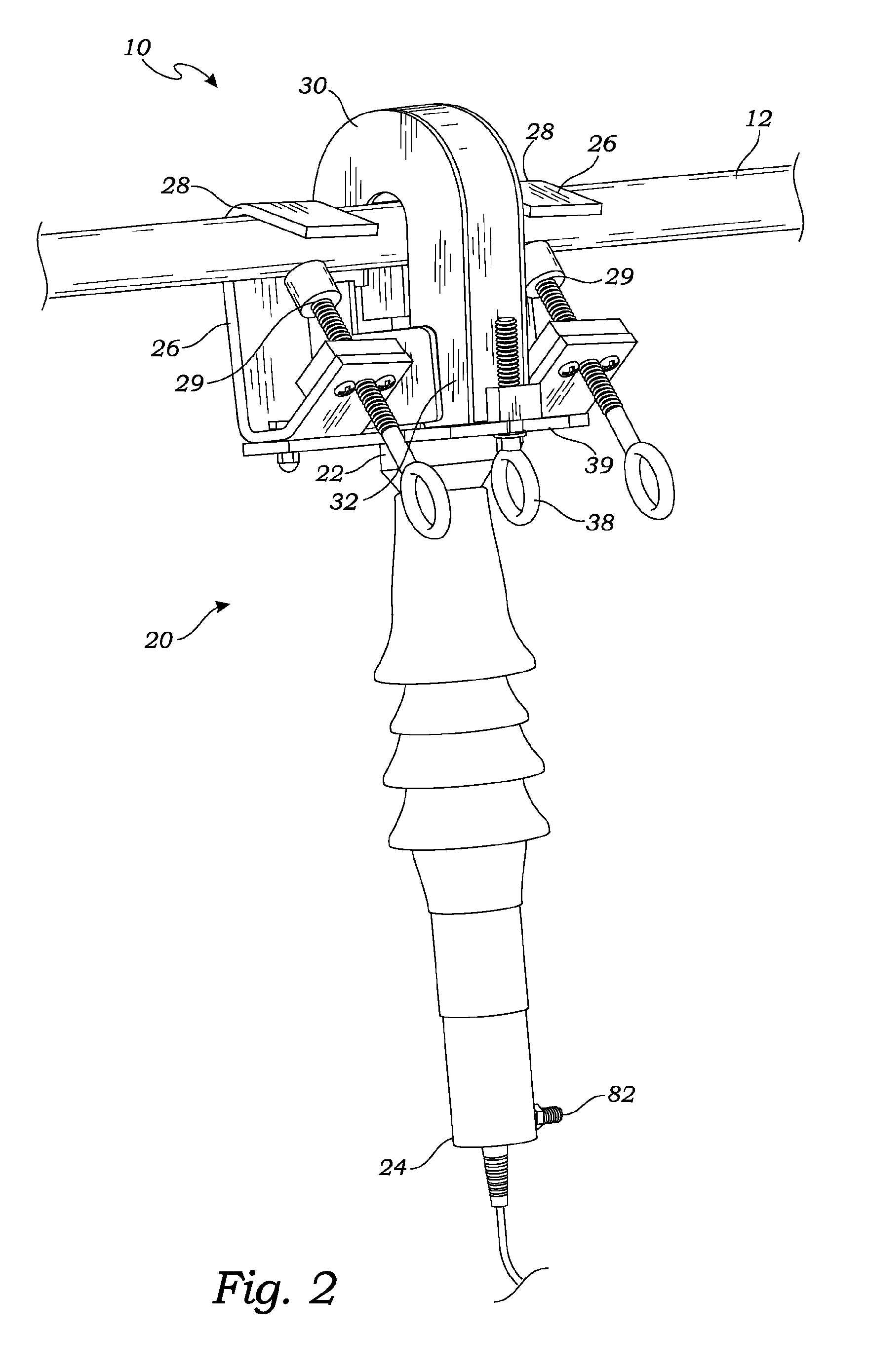
[0052]FIG. 2 is a perspective front view of FIG. 1, showing the magnetic concentrator in closed position showing housing 30 locked in place by locking element 38.

[0053]Referring to FIGS. 1 and 2, the base unit 20, which extends from hooks 26 to the bottom of the optical sensor assembly 10, uses two hooks 26, as shown, for hanging the base unit 20 from the current carrying cable 12. Only one hook, by itself, or, possibly, with additional ties, strapping or other structure may be used. In the embodiment of FIG. 1, a pair of hooks 26, one on either side of a light directing device 44, (which in one embodiment,...


PUM


Abstract

An optical sensor that senses current by directing polarized light across an airgap that is orthogonal to a direction of current running through a conductor. The sensor includes a prism having a high Verdet constant for high sensitivity to magnetic fields, which cause an angle of polarization of the polarized light to be rotated as an indication of the magnitude of current. A polarizing beamsplitter having a low Verdet constant is mounted to the prism so that incoming light that is traveling in a direction orthogonal to the magnetic field being sensed across the airgap is insensitive to unwanted magnetic fields produced by nearby conductors. The distance the light travels in this orthogonal direction is minimized, reducing the overall volume of the sensor, making a compact sensor highly sensitive to magnetic fields of interest, largely insensitive to unwanted magnetic fields, and having a very high dynamic range for sensing current.

Description

CROSS-REFERENCE TO RELATED APPLICATIONS[0001]This application claims the benefit of U.S. Provisional Patent Application Ser. No. 61 / 823,849, filed May 15, 2013, entitled, “Electro-Optic Current Sensor With High Dynamic Range and Accuracy,” and is a continuation-in-part of U.S. patent application Ser. No. 13 / 553,486, filed Jul. 19, 2012, entitled “Optical Sensor Assembly For Installation on a Current Carrying Cable,” both of which are hereby incorporated by reference herein in their entireties.FIELD OF THE PRESENT DISCLOSURE[0002]Aspects of the present disclosure relate to optical sensors, and more particularly, to optical sensors used to sense an electrical current in a current carrying cable.BACKGROUND[0003]A variety of sensors have been developed for measuring current in a current carrying cable, such as current in a high voltage electrical distribution system. Optical current sensors 30 based on the birefringence of various materials, and the Faraday effect, from the magnetic fie...

Claims


Application Information

Patent Timeline
IPC IPC(8): G01R19/00G01R15/14
CPCG01R15/142G01R19/00G01R15/246G01R1/071G01R15/247
Inventor DAVIS, PHILIP B.LI, YEKONETSKI, THEODORE C.
Owner MICATU
Why Eureka
Try Eureka