
Electrical connector having improved insulative housing

a technology of insulating housing and electric connector, which is applied in the direction of electric discharge lamps, coupling device connections, electric discharge tubes, etc., can solve the problems of easy snapping of the longitudinal base and inability to achieve excellent high-frequency characteristics, and achieve the effect of improving rigidity

Active Publication Date: 2014-10-16
HON HAI PRECISION IND CO LTD
View PDF30 Cites 1 Cited by
  • Summary
  • Abstract
  • Description
  • Claims
  • Application Information

AI Technical Summary

Benefits of technology

The objective of this patent is to improve the rigidity of an electrical connector by using a better insulative housing.

Problems solved by technology

However, the mating tongue is spaced from the mating frame with a gap provided therebetween, and the longitudinal base will be easily snapped in a portion corresponding to the gap.
Moreover, the first contact set is arranged upon a single mating tongue, which is not benefit for excellent high-frequency characteristics.

Method used


Image

  • Electrical connector having improved insulative housing
  • Electrical connector having improved insulative housing
  • Electrical connector having improved insulative housing

Examples


Embodiment Construction

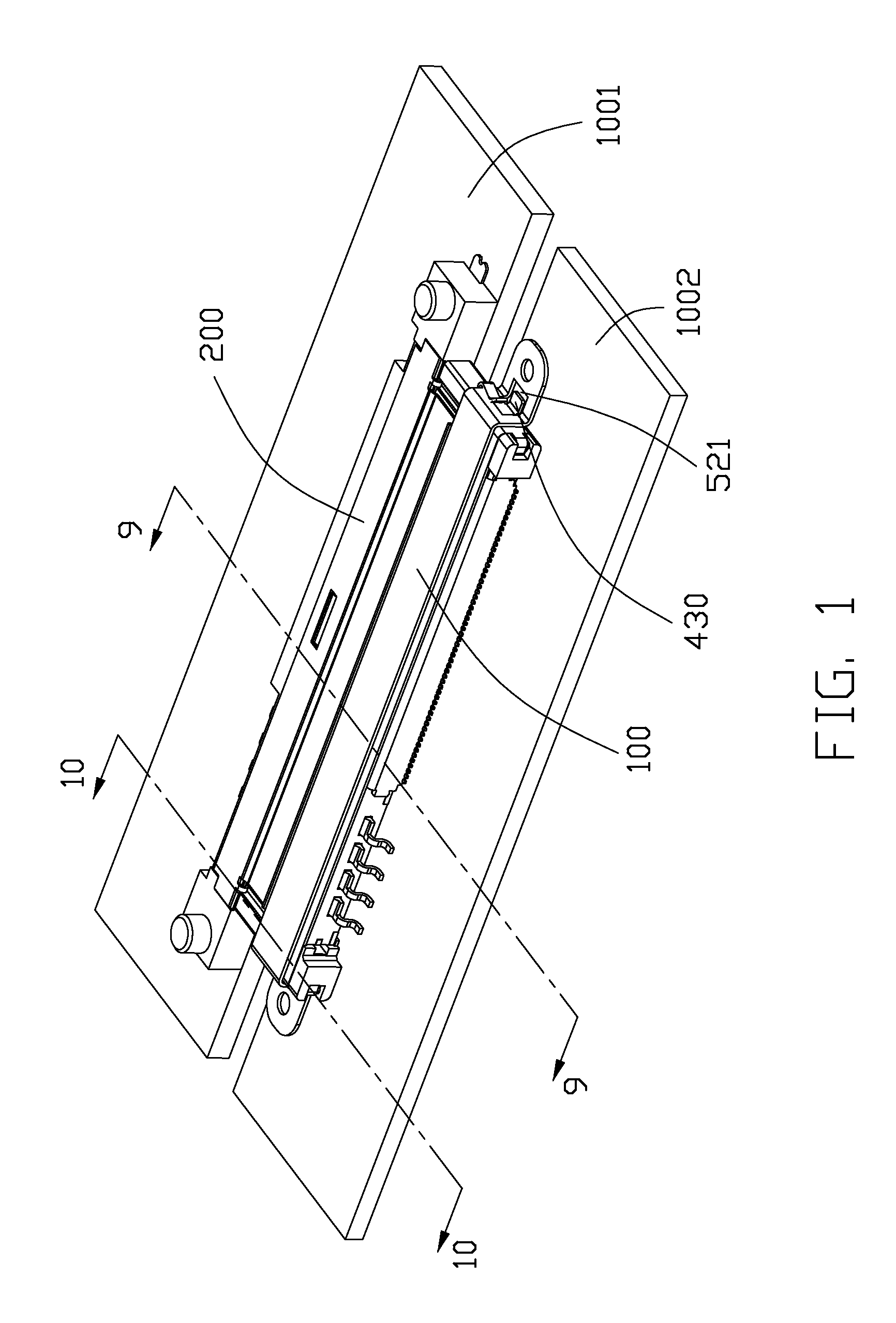
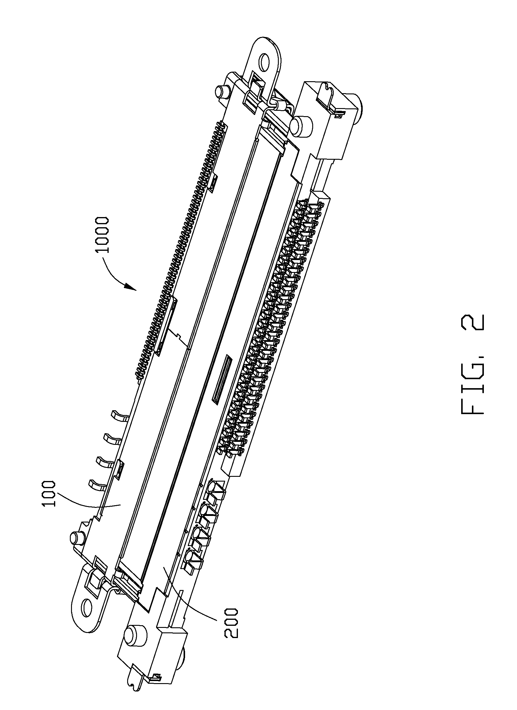
[0019]Reference will now be made to the drawing figures to describe a preferred embodiment of the present invention in detail. Referring to FIG. 1 and FIG. 2, an electrical connector assembly 1000 in accordance with the present invention includes an electrical connector 100, or a first connector, to be mounted onto a first printed circuit board 1002, and a mating connector 200, or a second connector, to be mounted onto a second printed circuit board 1001 for mating with the electrical connector 100.

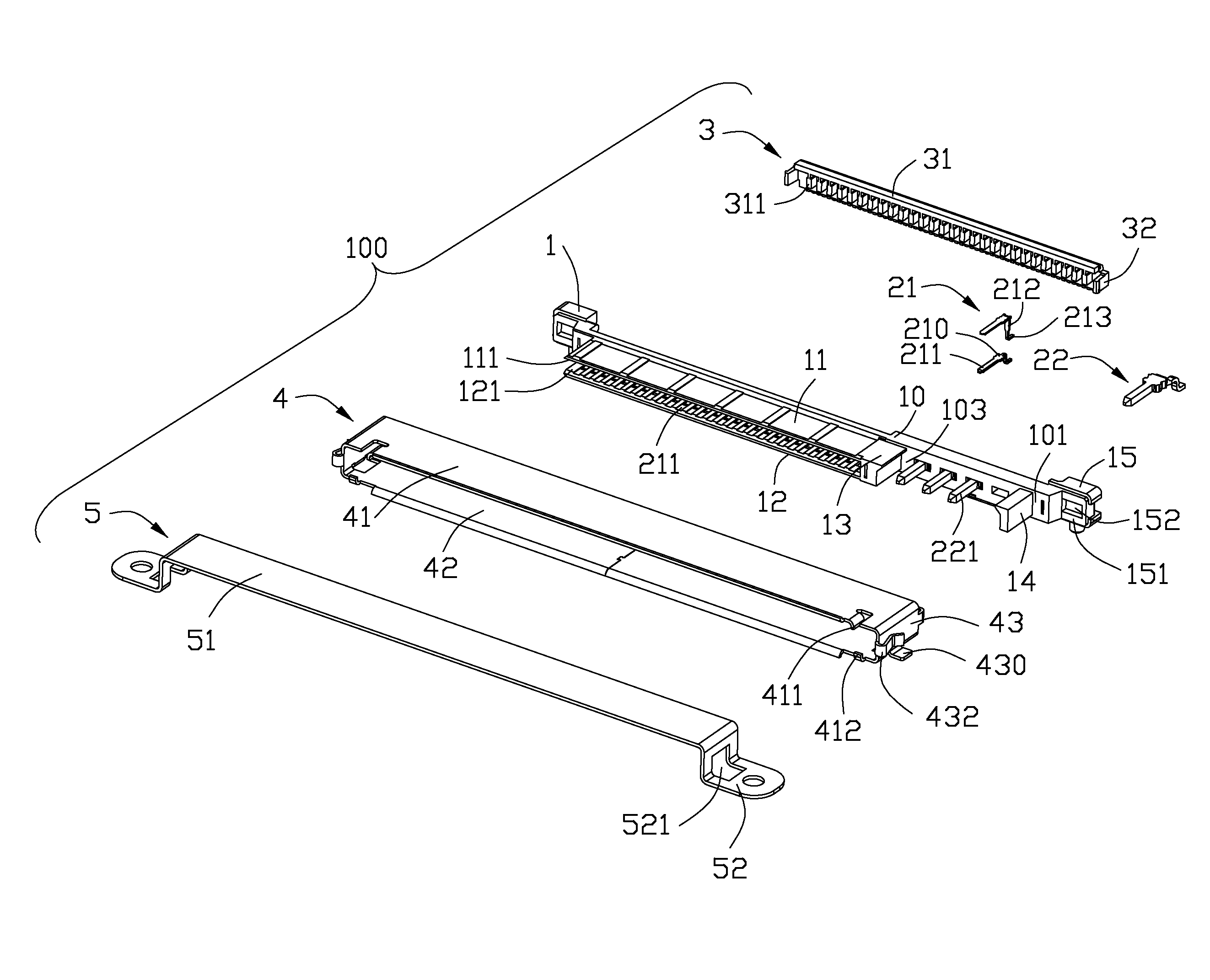
[0020]Referring to FIG. 3 to FIG. 5, the electrical connector 100 includes an insulative first housing 1, a plurality of contacts arranged in the first housing 1, a spacer 3 retained to the first housing 1, a metal shell 4 enclosing the first housing 1, and a retaining member 5 attached to the metal shell 4.

[0021]The first housing 1 defines a longitudinal base portion 10, a first and a second mating tongue 11, 12 extending forwardly from the base portion 10 along a front-to-rear direction...


PUM


Abstract

An electrical connector includes a first insulative housing having a first mating port and a second mating port arranged side by side, a plurality of first contacts retained to the first mating port, and a plurality of second contacts retained to the second mating port. The first mating port includes first and second mating tongues providing corresponding first and second mating faces opposite to each other. The second mating port defines a first strengthen arm adjacent to the first mating port to connect with the first and second mating tongues, the first contacts provide first contacting portions exposed upon both the first mating face and the second mating face.

Description

BACKGROUND OF THE INVENTION[0001]1. Field of the Invention[0002]The present invention relates to an electrical connector, and more particular to a complex electrical connector having improve insulative housing for improving the rigidity thereof and further an additional mounting bracket for securing to a printed circuit board.[0003]2. Description of the Related Art[0004]U.S. Pat. No. 7,946,887 issued on May 24, 2011 discloses an electrical connector assembly including a first connector and a second connector mating with each other. The first connector includes a longitudinal base and a plurality of contacts retained in the base. The base defines a mating tongue and a mating frame arranged side by side along the longitudinal direction, and a mating cavity is surrounded by the mating frame. The plurality of contacts are divided into a first contact set exposed upon a mating face of the mating tongue and a second contact set projecting into the mating cavity. The first connector has tw...

Claims


Application Information

Patent Timeline
IPC IPC(8): H01R12/71H01R24/58
CPCH01R24/58H01R12/71H01R12/722H01R12/732
Inventor YUAN, WEIHSIAO, YU-SANHSIAO, SHIH-WEI
Owner HON HAI PRECISION IND CO LTD
Learn More