Rotatable Orifice Plate for Direct Flow Measurement

a technology of direct flow and orifice plate, which is applied in the direction of liquid/fluent solid measurement, volume metering, instruments, etc., can solve the problems of scale or suspended matter build-up of permanent flow measurement devices in fluid flow systems, additional components in the system taking up extra space, and increasing the head loss in a pressure dependent system. , to achieve the effect of reducing the overall amount of components

Active Publication Date: 2014-10-23
FLUID HANDLING
View PDF0 Cites 8 Cited by
  • Summary
  • Abstract
  • Description
  • Claims
  • Application Information

AI Technical Summary

Benefits of technology

[0033]One advantage of the present invention is that it provides for a feature that enables direct flow measurement to be obtained through a valve in any system where there is fluid flowing. The present invention, which incorporates direct flow measurement in the sealing body or valve ball of the isolation valve reduces the overall amount of components needed in the system, and provides one head loss location when determining overall system head loss requirements, and positive shut-off.
is that it provides for a feature that enables direct flow measurement to be obtained through a valve in any system where there is fluid flowing. The present invention, which incorporates direct flow measurement in the sealing body or valve ball of the isolation valve reduces the overall amount of components needed in the system, and provides one head loss location when determining overall system head loss requirements, and positive shut-off.

Problems solved by technology

These additional components in the system take up extra space and increase the head loss in a pressure dependent system.
Permanent flow measurement devices in fluid flow systems are also subject to scale or suspended matter build up.

Method used


Image

  • Rotatable Orifice Plate for Direct Flow Measurement
  • Rotatable Orifice Plate for Direct Flow Measurement
  • Rotatable Orifice Plate for Direct Flow Measurement

Examples


Embodiment Construction

OF PARTICULAR EMBODIMENTS

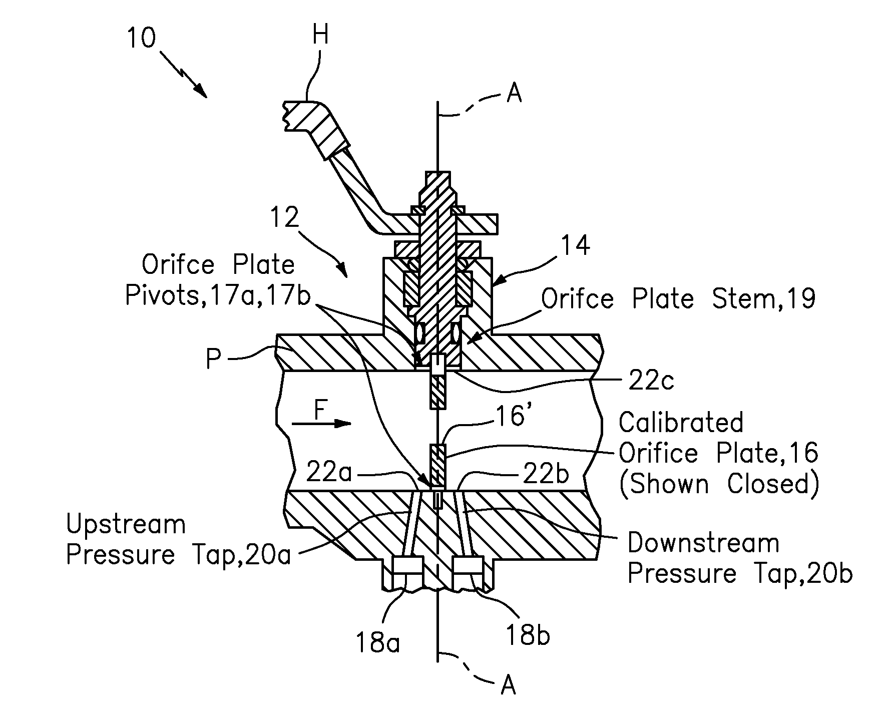
[0015]According to some embodiments, the present invention may take the form of apparatus, such as a valve comprising a valve housing or body in combination with a rotatable orifice plate.

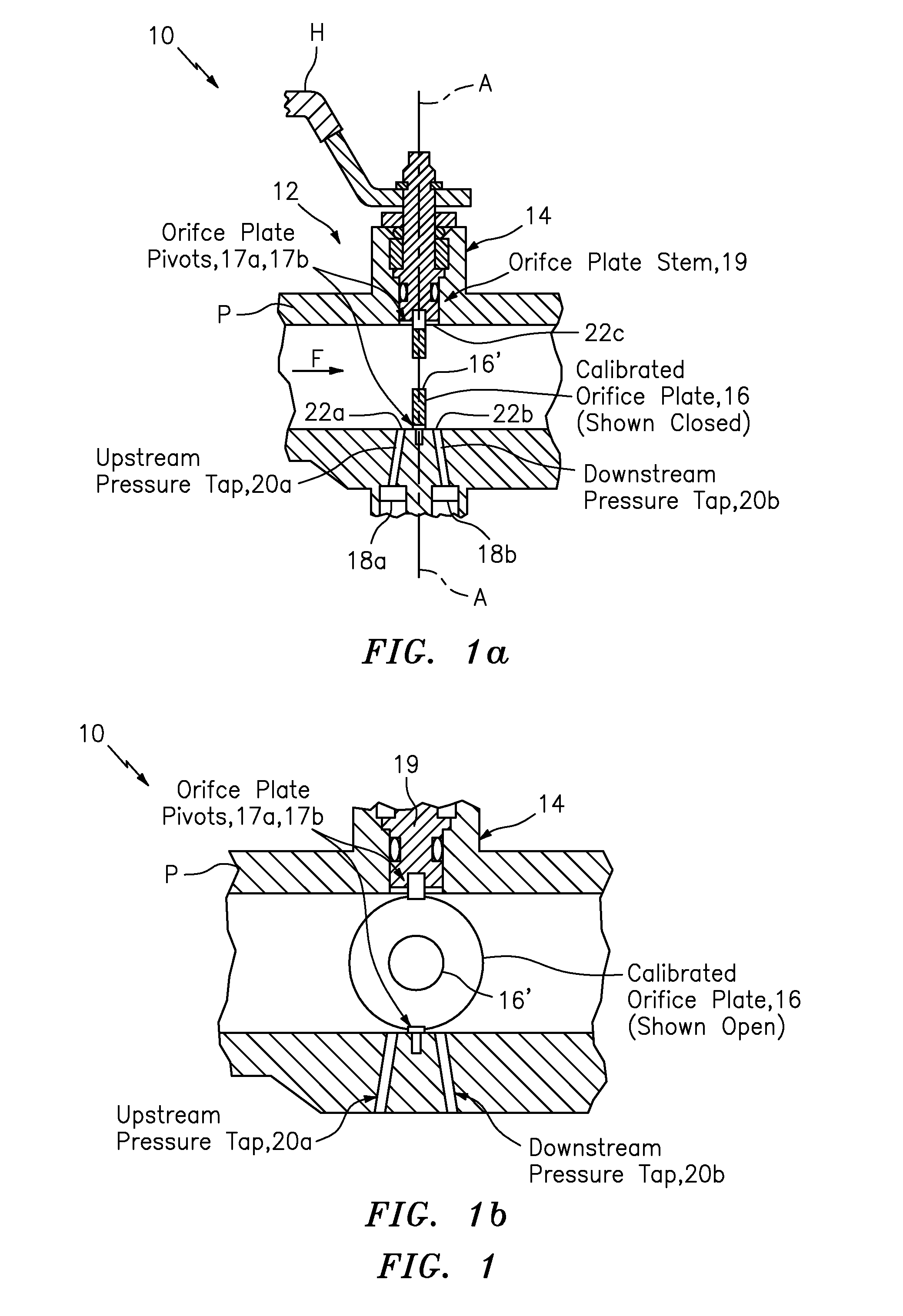
[0016]The valve body or housing may be configured to be arranged in, or form part of, a piping having a fluid flow, and also configured with at least one pressure tap arranged at at least one location along the piping to allow pressure of the fluid flow of the piping to be measured. The rotatable orifice plate having an orifice configured or formed therein, and configured to rotate in the valve body or housing on an axis of rotation positioned at a different location along the piping than the at least one pressure tap for rotating between a first rotatable position for providing a normal fluid flow operation and a second rotatable position substantially perpendicular to the fluid flow for providing a direct flow measurement of the fluid flow, so that the direct flow measure...


PUM


Abstract

A valve is provided having a valve housing / body configured to be arranged in, or form part of, a piping having a fluid flow, and configured with a pressure tap arranged at a location along the piping to allow pressure of the fluid flow of the piping to be measured, and also having a rotatable orifice plate configured to rotate in the valve body / housing on an axis of rotation positioned at a different location along the piping than the pressure tap for rotating between a first rotatable position for providing a normal fluid flow operation and a second rotatable position substantially perpendicular to the fluid flow for providing a direct flow measurement of the fluid flow determined based on signaling sensed by the pressure tap sensor containing information about a measured pressure at the pressure tap when the orifice plate is in the second rotatable position.

Description

CROSS-REFERENCE TO RELATED APPLICATIONS[0001]This application claims benefit to provisional application Ser. No. 61 / 756,814 (Atty docket no. F-B&G-X0006 / / 911-19.8-1), filed 25 Jan. 2013, which is hereby incorporated by reference in its entirety.[0002]This application is also a continuation-in-part of, and claims benefit to, application Ser. No. 13 / 681,628 (Atty docket no. F-B&G-X0003 / / 911-19.6-1), filed 20 Nov. 2012, which is hereby incorporated by reference in its entirety.BACKGROUND OF THE INVENTION[0003]1. Field of the Invention[0004]The present invention relates to a technique for providing a direct flow measurement; and more particularly, the present invention relates to a valve configured for providing a direct flow measurement.[0005]2. Brief Description of Related Art[0006]Presently, most known systems where a fluid flows at a constant rate require a separate permanent flow measurement device to verify the system flow rate. These additional components in the system take up ex...

Claims


Application Information

Patent Timeline
Patent Type & Authority Applications(United States)
IPC IPC(8): G01F1/42
CPCG01F1/42G01F1/40G01F1/44G01F15/005F16K5/0605Y10T137/6035
Inventor EVANS, STANLEY P.ROSCA, FLORINNAIR, MAHESHWELEKAR, AMIT
Owner FLUID HANDLING
Why Eureka
Try Eureka