Trigger-Operated Adhesive Tape Displenser
- Summary
- Abstract
- Description
- Claims
- Application Information
AI Technical Summary
Benefits of technology
Problems solved by technology
Method used
Image
Examples
Embodiment Construction
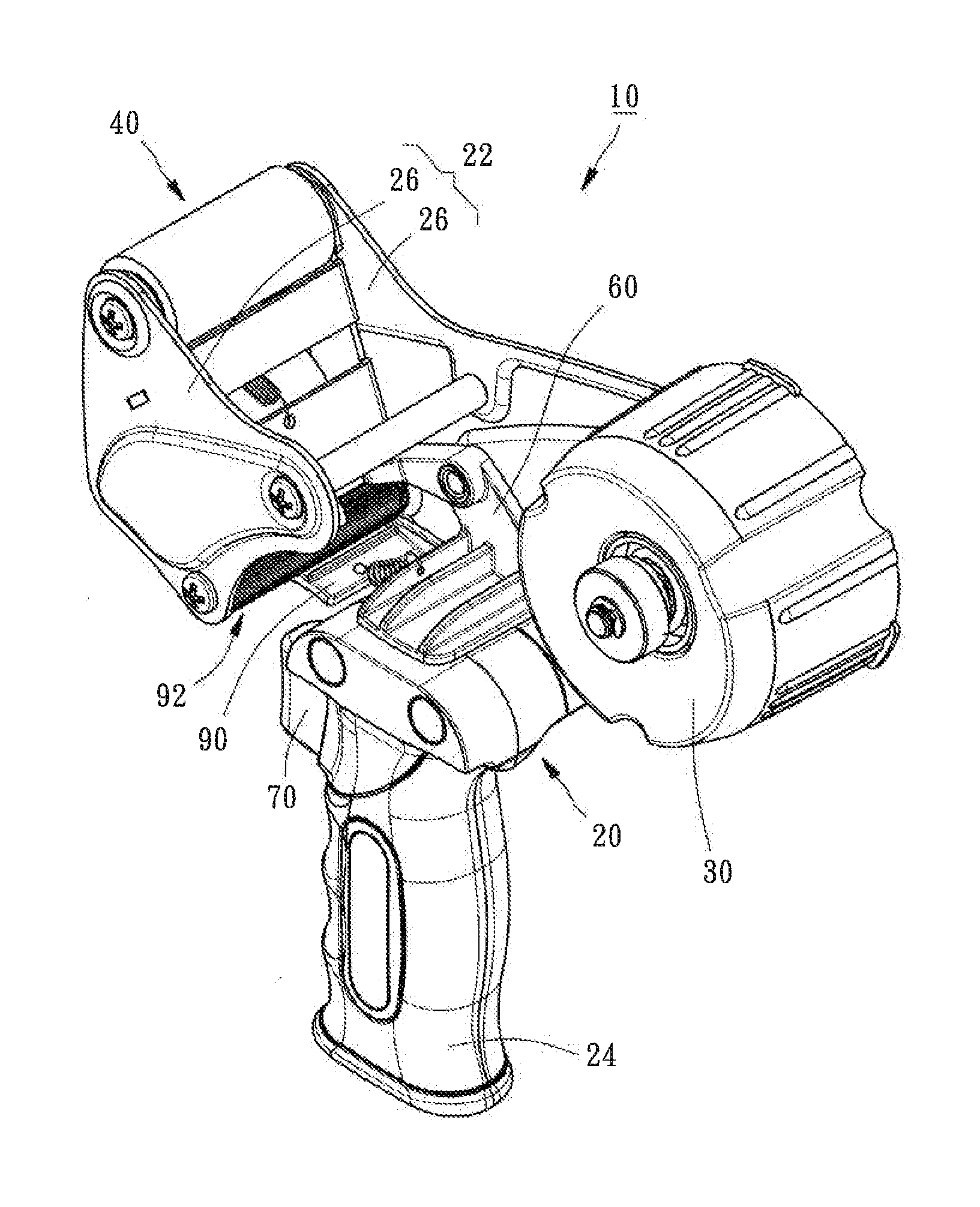
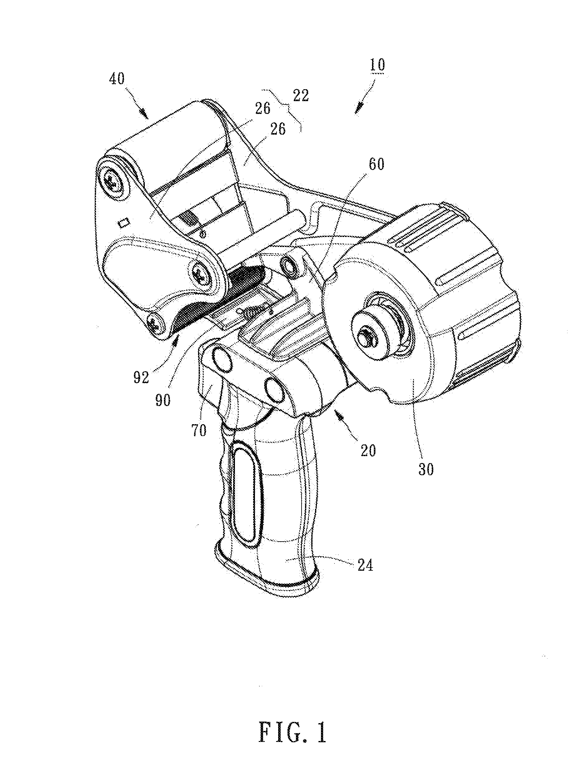
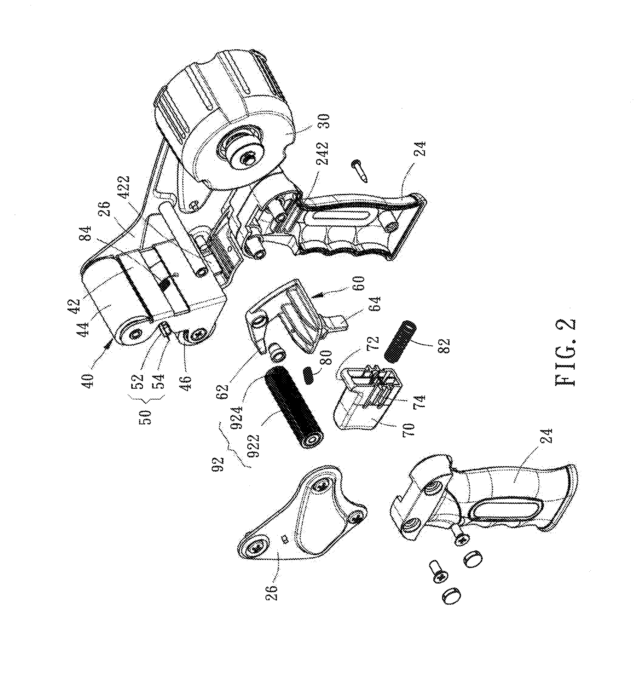
[0018]Referring to FIGS. 1 and 2, a trigger-operated adhesive tape dispenser 10 in accordance with the present invention is shown. The trigger-operated adhesive tape dispenser 10 comprises a support unit 20, a tape holder wheel 30, a swing unit 40, a cutting unit 50, a stopper member 60, a trigger 70, a first return member 80, and a second return member 82.
[0019]The support unit 20 comprises a rack 22 and a handle 24. The rack 22 is formed of two opposite side panels 26. However, this structural configuration is not a limitation. The handle 24 has a top end thereof fixedly connected to a bottom side of one side panel 26, and is configured for holding by the user. Further, the handle 24 defines a first guide portion 242 in each of two opposite inner sides thereof.
[0020]The tape holder wheel 30 is pivotally mounted at a rear side of one side panel 26 of the rack 22 of the support unit 20 for holding an adhesive tape roll 12 (see FIG. 6).
[0021]The swing unit 40 comprises a swing frame ...
PUM
| Property | Measurement | Unit |
|---|---|---|
| Time | aaaaa | aaaaa |
| Pressure | aaaaa | aaaaa |
Abstract
Description
Claims
Application Information
 - R&D
- Intellectual Property
- Life Sciences
- Materials
- Tech Scout
- Unparalleled Data Quality
- Higher Quality Content
- 60% Fewer Hallucinations
Browse by: Latest US Patents, China's latest patents, Technical Efficacy Thesaurus, Application Domain, Technology Topic, Popular Technical Reports.
© 2025 PatSnap. All rights reserved.Legal|Privacy policy|Modern Slavery Act Transparency Statement|Sitemap|About US| Contact US: help@patsnap.com


