
Trigger-operated adhesive tape displenser

a technology of trigger-operated dispensers and adhesive tapes, which is applied in the directions of paper hanging, transportation and packaging, chemistry apparatuses and processes, etc., can solve the problems of inconvenient operation of conventional adhesive tape dispensers, inconvenient cutting of adhesive tape, and inability to easily cut off adhesive tapes by the cutter blade, etc., to achieve convenient cutting, easy operation, and ease of use

Inactive Publication Date: 2015-02-17
HUANG HARRISON
View PDF3 Cites 5 Cited by
  • Summary
  • Abstract
  • Description
  • Claims
  • Application Information

AI Technical Summary

Benefits of technology

Enables effortless and easy operation by allowing the user to cut the adhesive tape with less effort and without repeated adjustments, improving the ease of use compared to conventional dispensers.

Problems solved by technology

If the downward pressure applied to adhesive tape dispenser is insufficient or the direction of the applied downward pressure is not correct, the applied adhesive tape will not be easily cut off by the cutter blade.
When this problem occurs, the user must repeatedly adjust the applied pressure and angle till that the adhesive tape can be smoothly cut off, Thus, the operation of the aforesaid conventional adhesive tape dispenser is inconvenient and requires much effort.

Method used


Image

  • Trigger-operated adhesive tape displenser
  • Trigger-operated adhesive tape displenser
  • Trigger-operated adhesive tape displenser

Examples


Embodiment Construction

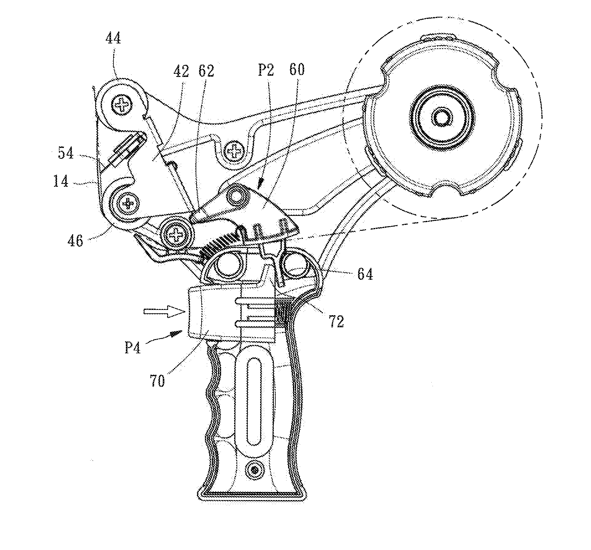
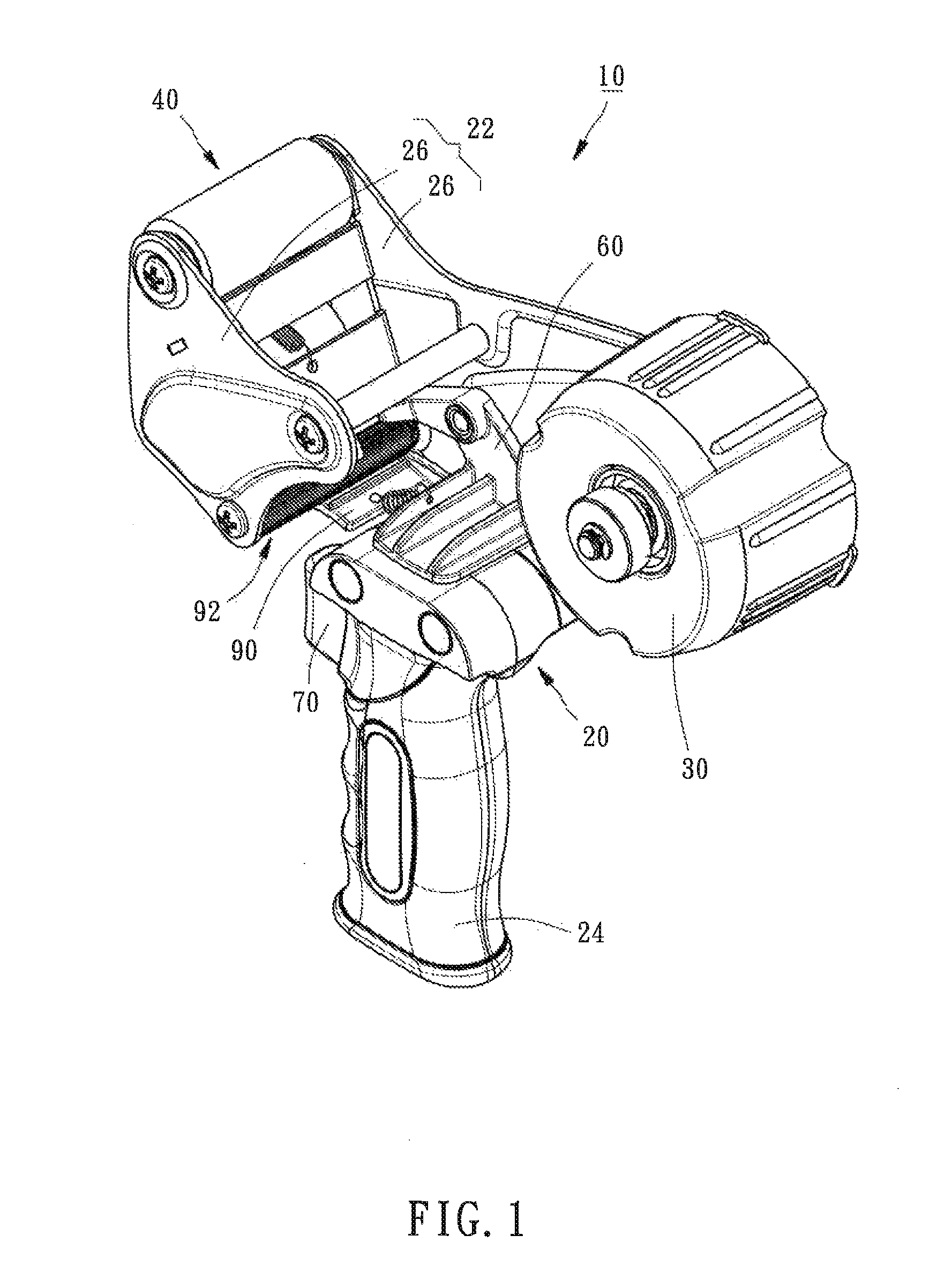
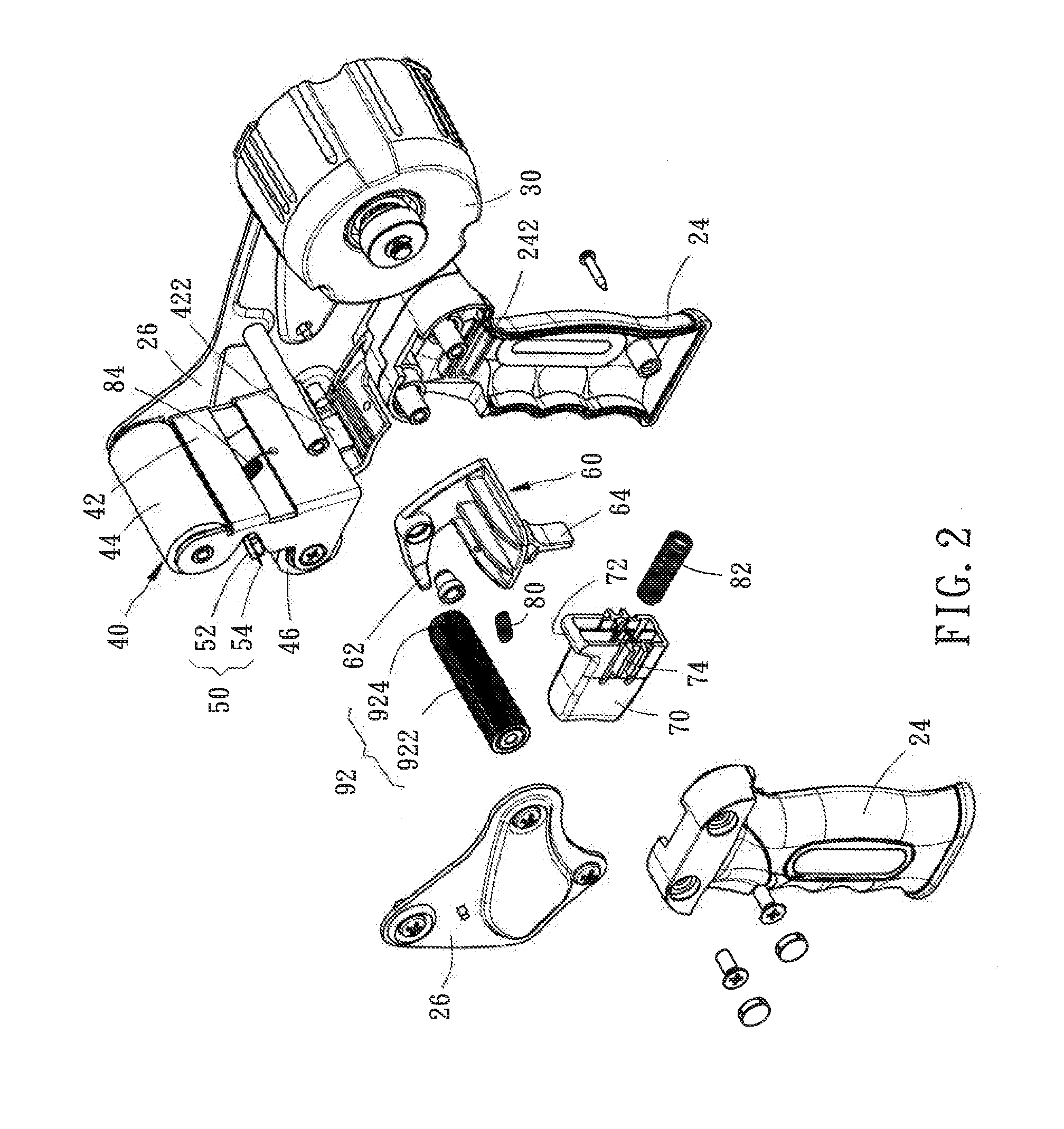
[0018]Referring to FIGS. 1 and 2, a trigger-operated adhesive tape dispenser 10 in accordance with the present invention is shown. The trigger-operated adhesive tape dispenser 10 comprises a support unit 20, a tape holder wheel 30, a swing unit 40, a cutting unit 50, a stopper member 60, a trigger 70, a first return member 80, and a second return member 82.

[0019]The support unit 20 comprises a rack 22 and a handle 24. The rack 22 is formed of two opposite side panels 26. However, this structural configuration is not a limitation. The handle 24 has a top end thereof fixedly connected to a bottom side of one side panel 26, and is configured for holding by the user. Further, the handle 24 defines a first guide portion 242 in each of two opposite inner sides thereof.

[0020]The tape holder wheel 30 is pivotally mounted at a rear side of one side panel 26 of the rack 22 of the support unit 20 for holding an adhesive tape roll 12 (see FIG. 6).

[0021]The swing unit 40 comprises a swing frame ...


PUM

PropertyMeasurementUnit
pressureaaaaaaaaaa
surface areaaaaaaaaaaa
lengthaaaaaaaaaa

Abstract

A trigger-operated adhesive dispenser includes a rack, a handle affixed to the rack, a swing frame pivotally mounted at the rack, a cutter blade fixedly mounted at the rack, a stopper member pivotally mounted at the rack, and a trigger mounted at the handle. When the trigger is not pressed, the swing frame is stopped by the stopper member and prohibited from being biased, allowing the adhesive tape to be pulled out and adhered to the object to be packed. When pressing the trigger, the trigger will push the stopper member to release the swing frame, enabling the swing frame to be biased, and thus the cutter blade can forced to cut off the applied adhesive tape.

Description

BACKGROUND OF THE INVENTION[0001]1. Field of the Invention[0002]The present invention relates to adhesive tape dispensing technology and more particularly, to a trigger-operated adhesive tape dispenser.[0003]2. Description of the Related Art[0004]When using a conventional adhesive tape dispenser, it is to adhere one end of the adhesive tape of the loaded adhesive tape roll to the surface area of the object to the packed, and then move the adhesive tape dispenser to pull the adhesive tape out of the adhesive tape roll subject to the desired length. During rotation of the tae holder wheel to let off the adhesive tape of the adhesive tape roll, the adhesive tape is smoothly adhered to the surface of the object. At final, use the cutter blade to cut off the applied adhesive tape. Thus, the use of the adhesive tape dispenser can effectively simplify the packing process and enhance the packing efficiency.[0005]However, before cutting off the applied adhesive tape, the user must rotate the...

Claims


Application Information

Patent Timeline
Patent Type & Authority Patents(United States)
IPC IPC(8): B29C65/00B44C7/00B65H35/06
CPCB65H35/06B29C65/00B44C7/00B65H35/0033B65H35/0086B65H2402/412Y10T156/12Y10T156/1348Y10T156/1365Y10T156/1795Y10T156/18
Inventor HUANG, HARRISON
Owner HUANG HARRISON
Learn More