
Tire cutting device

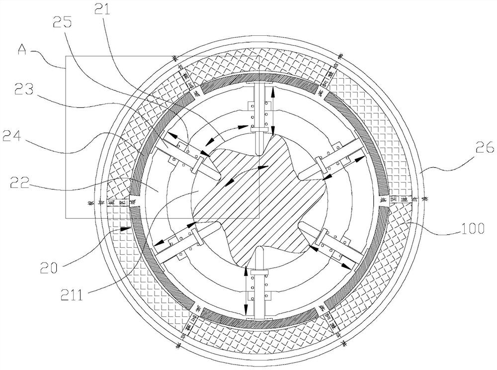
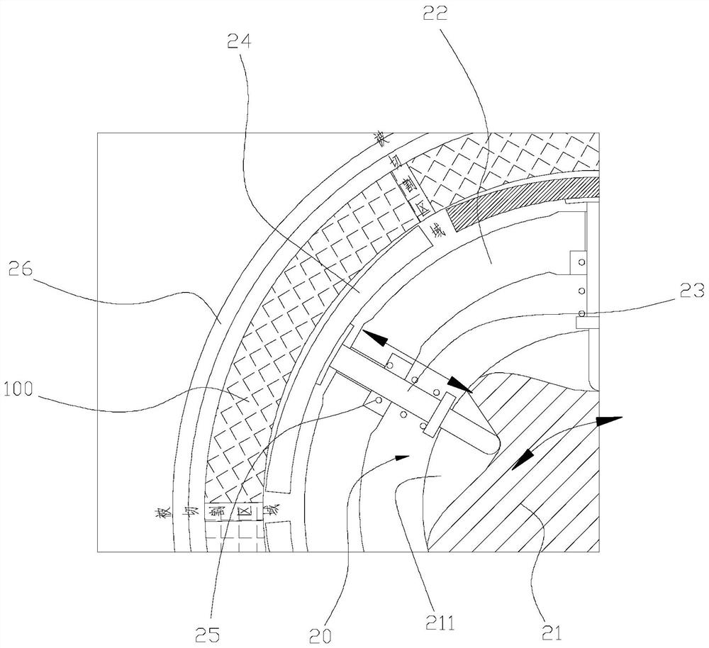
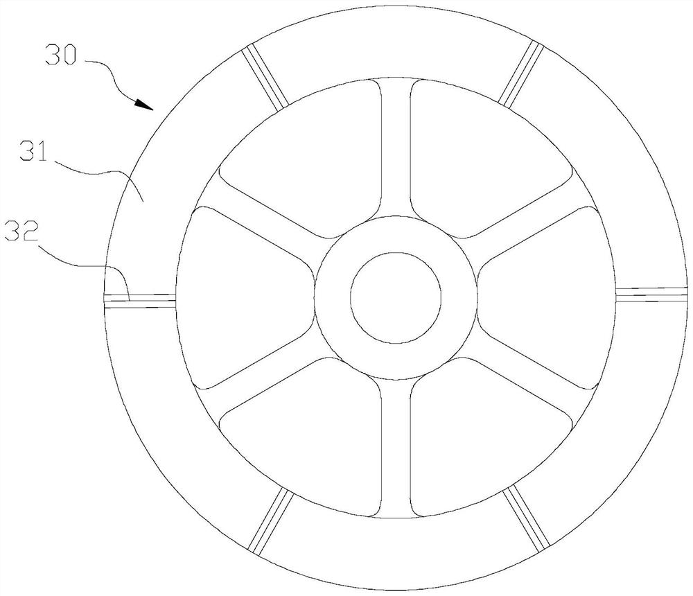
A cutting device and tire technology, which is applied in recycling technology, metal processing, plastic recycling, etc., can solve the problems of difficult cutting of areas and difficult cutting process of cutters, and achieve the effect of ingenious design, easy cutting and convenient operation

Inactive Publication Date: 2020-12-18
天长市永南橡塑制品有限公司
View PDF10 Cites 0 Cited by
  • Summary
  • Abstract
  • Description
  • Claims
  • Application Information

AI Technical Summary

Problems solved by technology

[0004] The tire is a flexible part. When the cutter cuts the tire, the area close to the tread of the tire will have a large elastic deformation. cut off

Method used


Image

  • Tire cutting device
  • Tire cutting device
  • Tire cutting device

Examples


Embodiment Construction

[0033] Unless otherwise defined, the technical terms or scientific terms used in the present invention shall have the usual meanings understood by those skilled in the art to which the present invention belongs. "First", "second" and similar words used in the present invention do not indicate any order, quantity or importance, but are only used to distinguish different components. "Comprising" or "comprising" and similar words mean that the elements or items appearing before the word include the elements or items listed after the word and their equivalents, without excluding other elements or items. Words such as "connected" or "connected" are not limited to physical or mechanical connections, but may include electrical connections, whether direct or indirect. "Up", "Down", "Left", "Right" and so on are only used to indicate the relative positional relationship. When the absolute position of the described object changes, the relative positional relationship may also change acc...


PUM


Abstract

The invention discloses a tire cutting device. The tire cutting device comprises a working platform, a clamping mechanism and a disc-shaped knife; the clamping mechanism comprises a retaining sleeve,a rotating column body and telescopic shafts, the retaining sleeve is fixed on the working platform, and a tire is used for being arranged outside the retaining sleeve in a sleeving mode; the rotatingcolumn body is located in the retaining sleeve and can rotate, the plurality of telescopic shafts are arranged in the circumferential direction, and each telescopic shaft penetrates through the retaining sleeve; the disc-shaped knife comprises a disc body and a plurality of cutting knives, and the disc-shaped knife moves downwards to enable the cutting knives to cut the tire; a plurality of driving grooves are formed in the peripheral surface of the rotating column body in the circumferential direction, and each driving groove is gradually shallower in the extending direction in the circumferential direction; and supporting parts are arranged at the radial outer ends of the telescopic shafts. When the rotating column body rotates to enable the groove bottoms of the driving grooves to be in sliding fit with the telescopic shafts, the telescopic shafts move outwards in the radial direction to enable the supporting parts to extend into the tire in the radial direction, and each cutting knife is used for cutting the area, corresponding to the position between every two adjacent supporting parts, of the tire.

Description

technical field [0001] The invention relates to a tire cutting device. Background technique [0002] After the waste tires are recycled, the tires need to be cut. First, the tires are cut into several sections using a tire cutting device. Specifically, the tire cutting device includes: a placement platform and a disc cutter; the tire is placed on the placement platform, A plurality of cutting knives are arranged circumferentially on the lower surface of the disc-shaped cutter, and the disc-shaped cutter is moved toward to cut the tire. [0003] However, the above-mentioned tire cutting device in the prior art has the following defects when cutting tires: [0004] The tire is a flexible part. When the cutter cuts the tire, the area close to the tread of the tire will have a large elastic deformation. cut off. Contents of the invention [0005] Aiming at the above-mentioned technical problems existing in the prior art, an embodiment of the present invention provides a tir...

Claims


Application Information

Patent Timeline
IPC IPC(8): B26D1/09B26D3/24B26D7/01B29B17/00
CPCB26D1/09B26D3/24B26D7/01B29B17/00B29B2017/0021Y02W30/62
Inventor 王永南
Owner 天长市永南橡塑制品有限公司
Learn More