Shielding assembly and electronic device employing same

a technology of shielding assembly and electronic device, which is applied in the direction of color television details, television systems, instruments, etc., can solve the problem that the glass piece affects the appearance of the electronic device in some degr

Active Publication Date: 2014-10-23
FIH (HONG KONG) LTD
View PDF6 Cites 9 Cited by
  • Summary
  • Abstract
  • Description
  • Claims
  • Application Information

AI Technical Summary

Problems solved by technology

However, the glass piece affects an appearance of the electronic device to some extent.

Method used


Image

  • Shielding assembly and electronic device employing same
  • Shielding assembly and electronic device employing same
  • Shielding assembly and electronic device employing same

Examples


Embodiment Construction

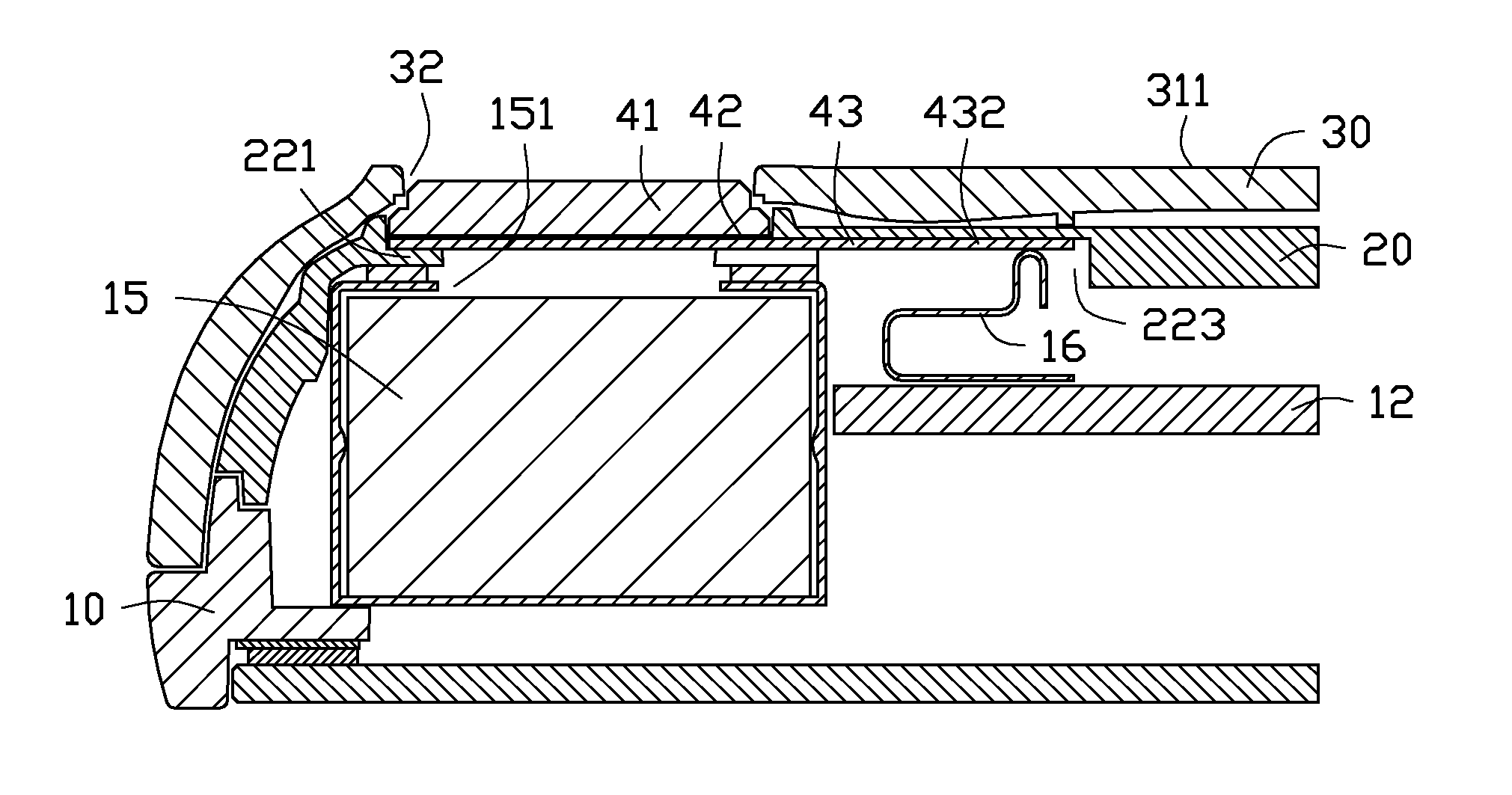
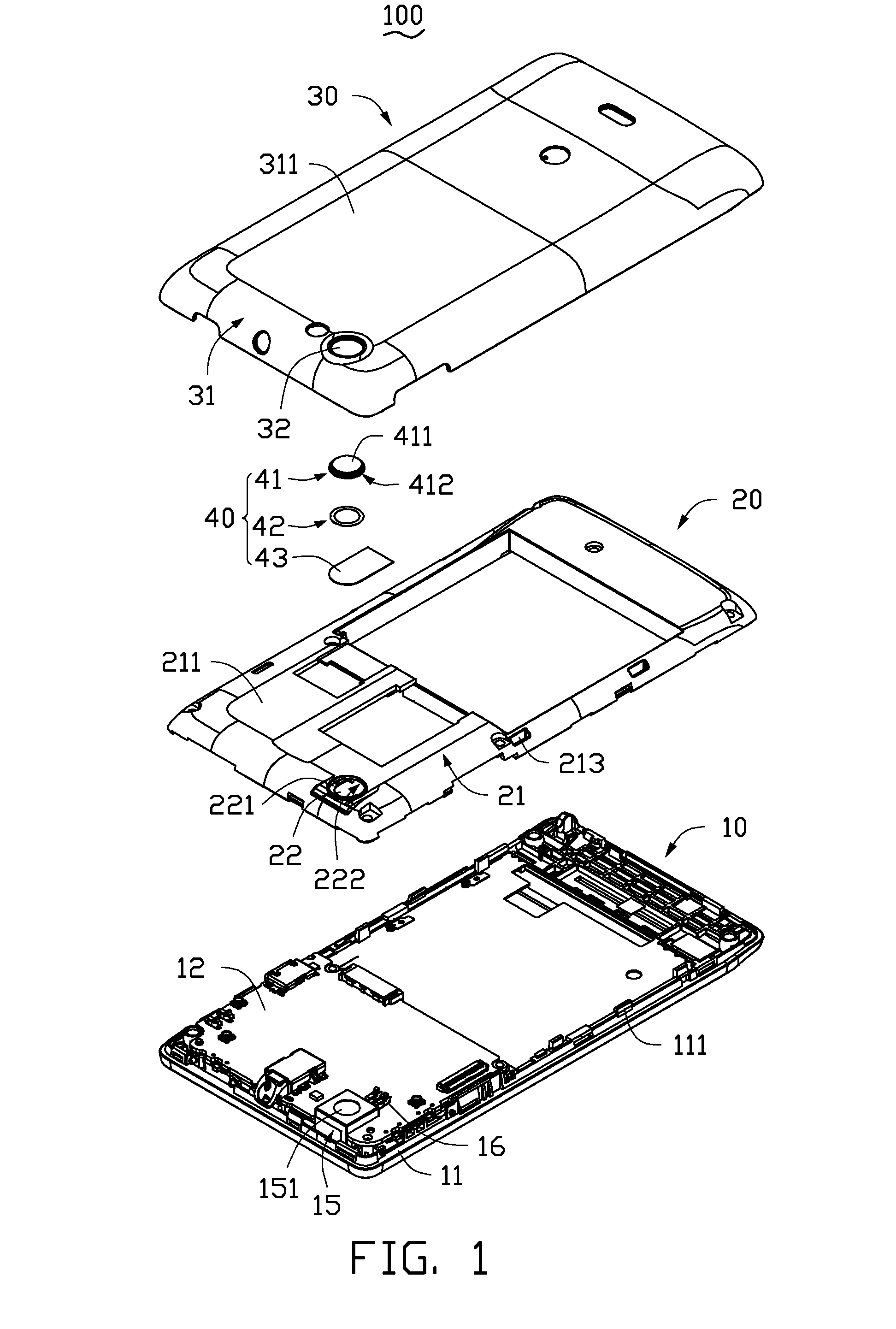
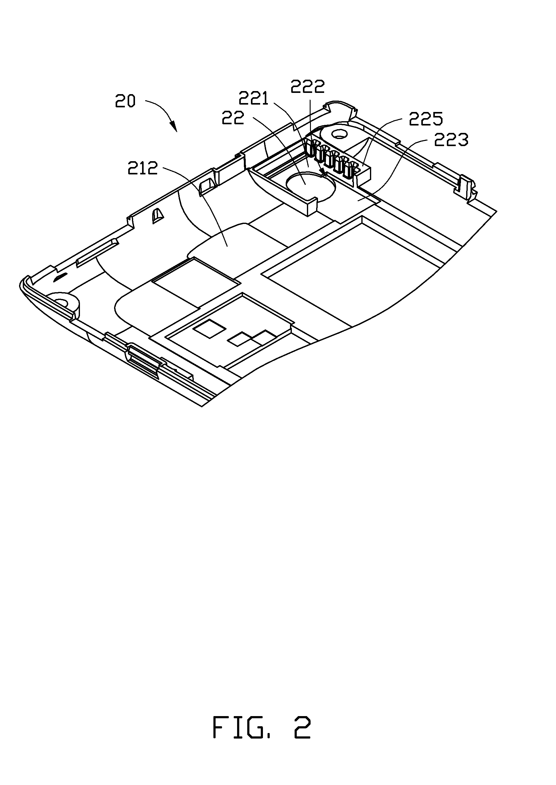
[0012]FIG. 1 is a shielding assembly 40 according to an exemplary embodiment. The shielding assembly 40 is applied to an electronic device 100, such as a mobile phone, a tablet computer, or a notebook computer, having a camera module 15. The electronic device 100 includes a main body 10, a first housing 20, a second housing 30, and the shielding assembly 40. The first housing 20 and the second housing 30 are both mounted on the main body 10, and the first housing 20 is located between the second housing 30 and the main body 10. In the present embodiment, the shielding assembly 40 is mounted in the electronic device 100 for covering the camera module 15.

[0013]The main body 10 includes a panel 11, a circuit board 12 mounted on the panel 11, a camera module 15 mounted on the circuit board 12, and two metal pieces 16. The camera module 15 is electrically connected to the circuit board 12. The camera module 15 includes a camera lens 151. The two metal pieces 16 are arranged on the circui...


PUM

PropertyMeasurementUnit
transparentaaaaaaaaaa
flexibleaaaaaaaaaa
diameteraaaaaaaaaa

Abstract

An electronic device includes a camera module and a shielding assembly. The shielding assembly includes at least one window glass and a smart film mounted to the window glass. The shielding assembly covers the camera module by turning opaque. If the camera module is in use, the shielding assembly is provided with electricity, and changes transparent. If the shielding assembly is not being provided with electricity, the shielding module becomes opaque to blind the camera module. A shielding assembly is also provided.

Description

BACKGROUND[0001]1. Technical Field[0002]The present disclosure relates to a shielding assembly for protecting a camera module of an electronic device, especially to a shielding assembly and an electronic device employing same.[0003]2. Description of Related Art[0004]Electronic devices such as mobile phones have camera modules. A housing of the electronic device defines a camera hole for the camera module. A transparent piece (e.g., glass) is mounted in the camera hole for allowing access for light and to protect the camera parts from contamination by dust and water. The camera module can be clearly observed by a user of the electronic device through the glass piece. However, the glass piece affects an appearance of the electronic device to some extent.BRIEF DESCRIPTION OF THE DRAWINGS[0005]Many aspects of the disclosure can be better understood with reference to the following figures. The components in the figures are not necessarily drawn to scale, the emphasis instead being placed...

Claims


Application Information

Patent Timeline
Patent Type & Authority Applications(United States)
IPC IPC(8): G02F1/153H04N5/225G02F1/137
CPCG02F1/153H04N5/2254G02F1/137H04N23/57H04N23/55
Inventor MIAO, YI-CHIEH
Owner FIH (HONG KONG) LTD
Why Eureka
Try Eureka