
Neutral-point-clamped multilevel power conversion device

a power conversion device and multi-level technology, applied in power conversion systems, ac-dc conversion, electrical equipment, etc., can solve problems such as interference between bias values

Inactive Publication Date: 2014-10-23
MEIDENSHA ELECTRIC MFG CO LTD
View PDF1 Cites 9 Cited by
  • Summary
  • Abstract
  • Description
  • Claims
  • Application Information

AI Technical Summary

Benefits of technology

The invention provides a power conversion device where the on-pulse bias voltage and the neutral-point bias voltage do not interfere with each other.

Problems solved by technology

Because of this, both bias values interfere with each other.

Method used


Image

  • Neutral-point-clamped multilevel power conversion device
  • Neutral-point-clamped multilevel power conversion device
  • Neutral-point-clamped multilevel power conversion device

Examples


embodiment

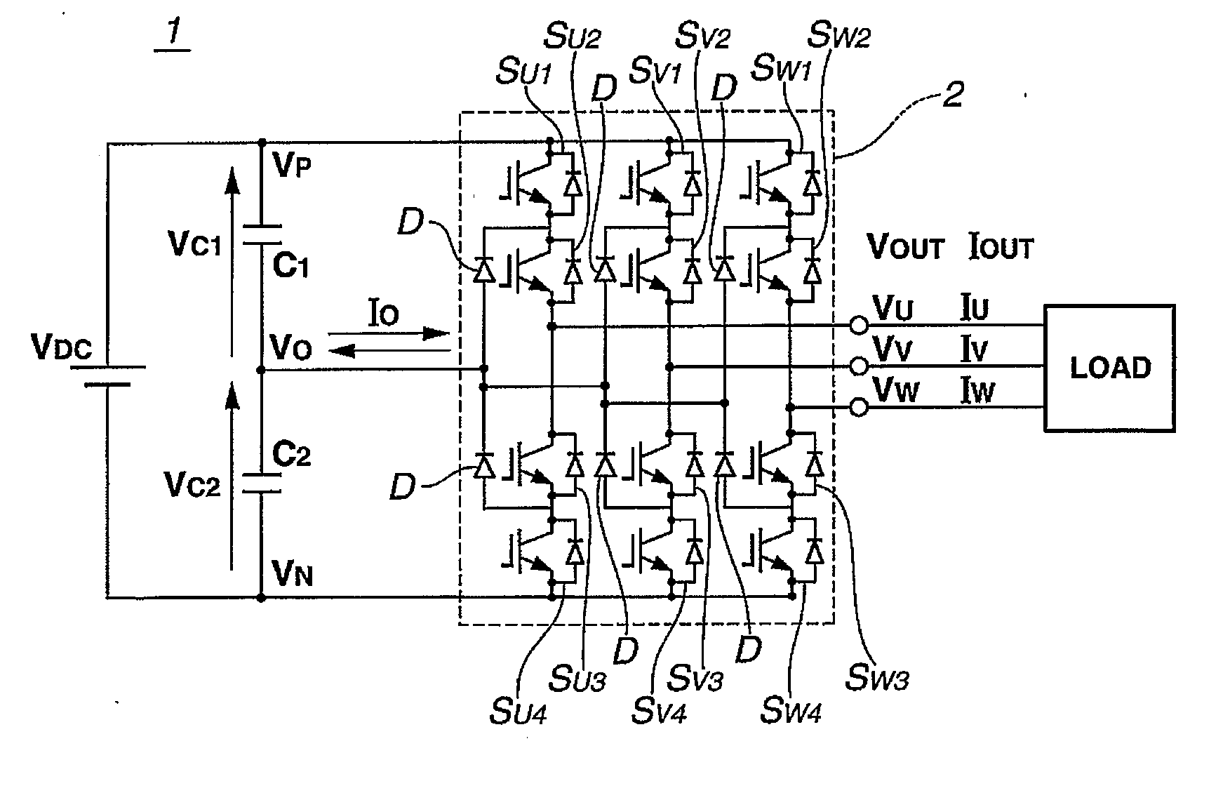
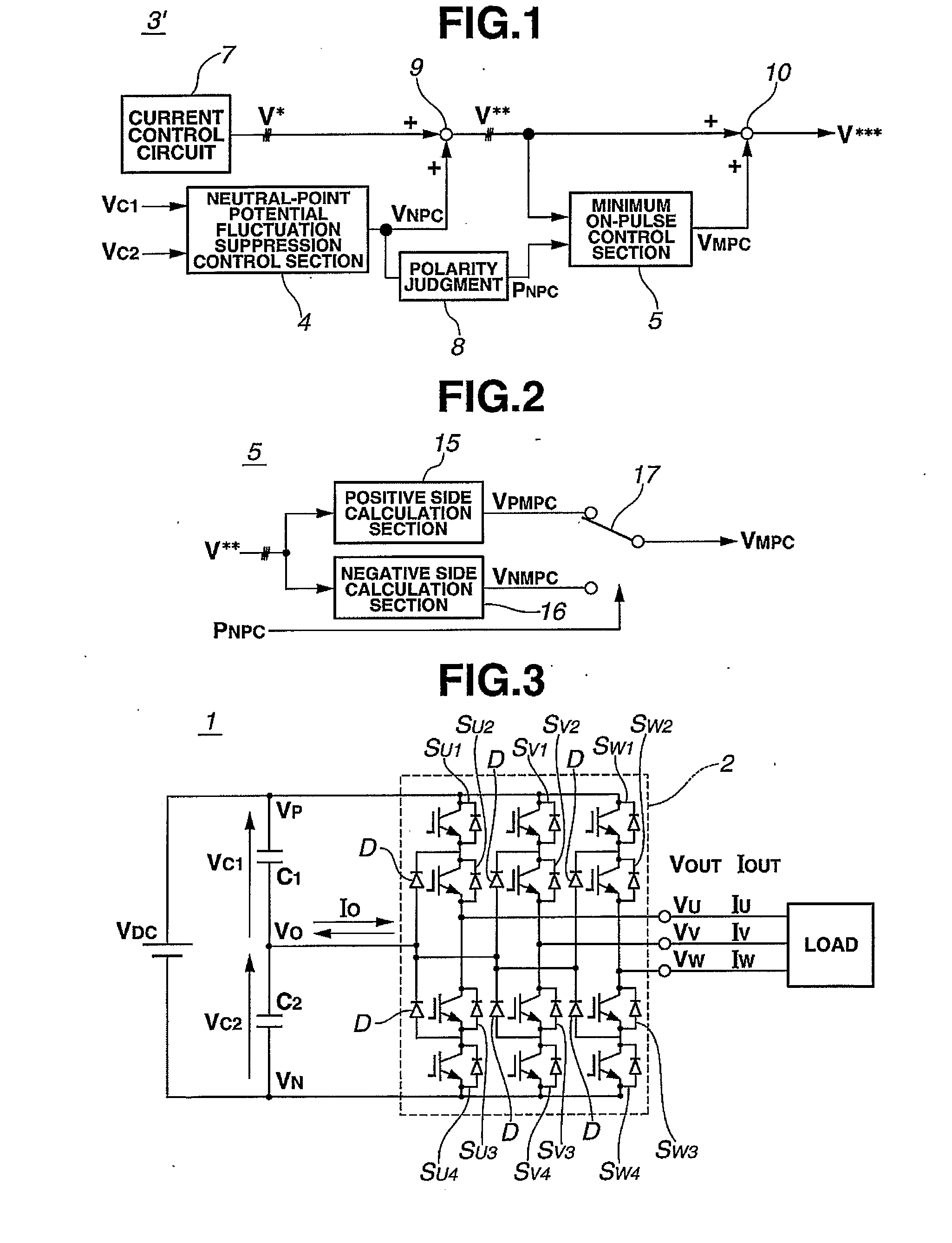
[0035]First, a configuration of a power conversion device 1 to which a general NPC power converter 2 is applied will be explained with reference to FIG. 3. The NPC power converter 2 is a converter in which first, second, third and fourth switching elements (e.g. SU1, SU2, SU3 and SU4) are sequentially connected in series between a positive electrode and a negative electrode of a DC power supply having a neutral-point output terminal, a connect ion point between the first and second switching elements SU1 and SU2 and a connection point between the third and fourth switching elements SU3 and SU4 are each connected to the neutral-point output terminal through a clamping element such as a diode D, and a connection point between the second and third switching elements SU2 and SU3 becomes an output terminal. FIG. 3 shows a three-phase NPC power converter formed by providing three sets of this single-phase circuit.

[0036]A gate signal, which is generated by comparing positive and negative t...


PUM


Abstract

The present invention provides a power conversion device in which an on-pulse bias voltage and a neutral-point bias voltage do not interfere with each other. A power conversion device 1 of the present invention has a polarity judgment section 8 that judges a polarity of a neutral-point bias voltage VNPC calculated by a neutral-point potential fluctuation suppression control section 4 of a voltage command value control circuit 3, then on the basis of this polarity of the neutral-point bias voltage VNPC, selects a polarity of an on-pulse bias voltage VMPC by an on-pulse control section 5. With this control, it is possible to prevent for the polarities of the neutral-point bias voltage VNPC and the on-pulse bias voltage VMPC from being different then prevent for the both bias voltages from interfering with each other.

Description

TECHNICAL FIELD[0001]The present invention relates to a neutral-point-clamped multilevel power conversion device (hereinafter called an NPC power converter), and more particularly to an NPC power converter that prevents degradation in response of a neutral-point potential fluctuation suppression control while securing on-pulse of a switching element.BACKGROUND ART[0002]A configuration of a conventional general NPC power converter is shown in FIG. 3. In the following description, a minimum on-pulse width control and a neutral-point potential fluctuation suppression control of the NPC power converter will be explained with reference to FIG. 3.[0003][Minimum on-Pulse Width Control][0004]In a case where a switching element (e.g. GTO) that has a limit on a minimum value of an on-pulse width (time) is used for switching elements SU1˜SU4, SV1˜SV4 and SW1˜SW4 of a three-phase NPC power converter 2, a pulse signal that is shorter than the limit of the minimum value of the on-pulse width migh...

Claims


Application Information

Patent Timeline
Patent Type & Authority Applications(United States)
IPC IPC(8): H02M7/487
CPCH02M7/487H02M1/12H02M1/14H02M7/521H02M7/537
Inventor URUSHIBATA, SHOTAMUNESHIMA, MASAKAZUZHANG, HUI
Owner MEIDENSHA ELECTRIC MFG CO LTD
Features
  • Generate Ideas
  • Intellectual Property
  • Life Sciences
  • Materials
  • Tech Scout
  • Unparalleled Data Quality
  • Higher Quality Content
  • 60% Fewer Hallucinations
Learn More