Dental forceps

a technology of dental forceps and abutments, which is applied in the field of dental forceps, can solve the problems of difficult to remove the restoration, the abutment screw loosening is a challenging complication, and the abutment from the underlying abutment is difficult to locate, so as to achieve a simple mechanical advantage

Inactive Publication Date: 2014-10-23
CHANG KIM +1
View PDF4 Cites 6 Cited by
  • Summary
  • Abstract
  • Description
  • Claims
  • Application Information

AI Technical Summary

Benefits of technology

[0007]In one aspect, the invention comprises an improved dental forceps, which uses simple mechanical advantage by employing first-class lever mechanics, for extracting a first tooth or crown positioned adjacent or nearby a second tooth. In one embodiment, the dental forceps comprise:

Problems solved by technology

With the increased use of cementation, loosening of an abutment screw is a challenging complication of cement-retained, implant-supported prosthetic restorations.
In such situations, separating the cemented crown from the underlying abutment or locating the abutment-screw access for removal of the restoration is a difficult task.

Method used


Image

  • Dental forceps
  • Dental forceps
  • Dental forceps

Examples


Embodiment Construction

[0024]The present invention relates to improved dental forceps. Any term or expression not expressly defined herein shall have its commonly accepted definition understood by those skilled in the art.

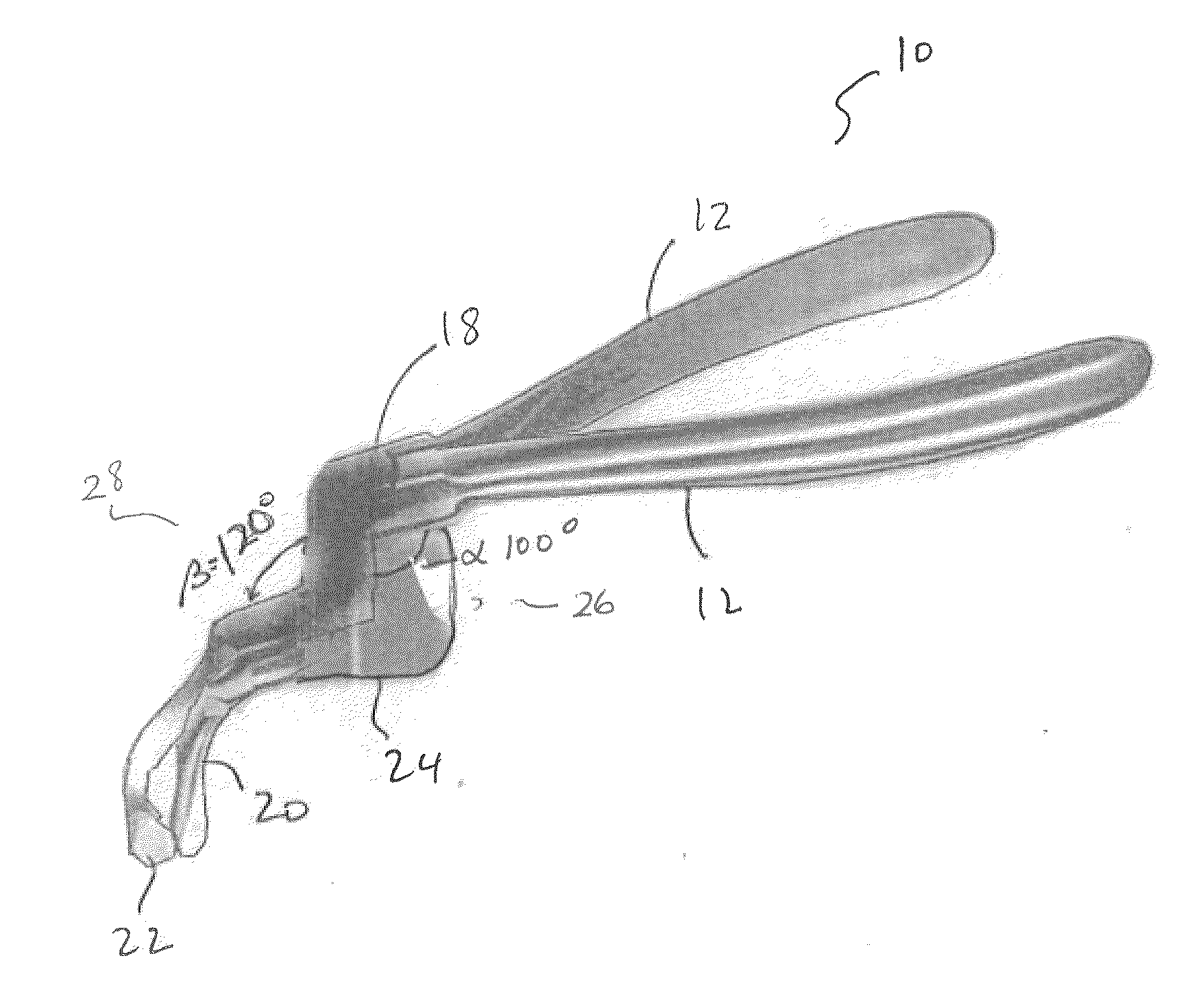
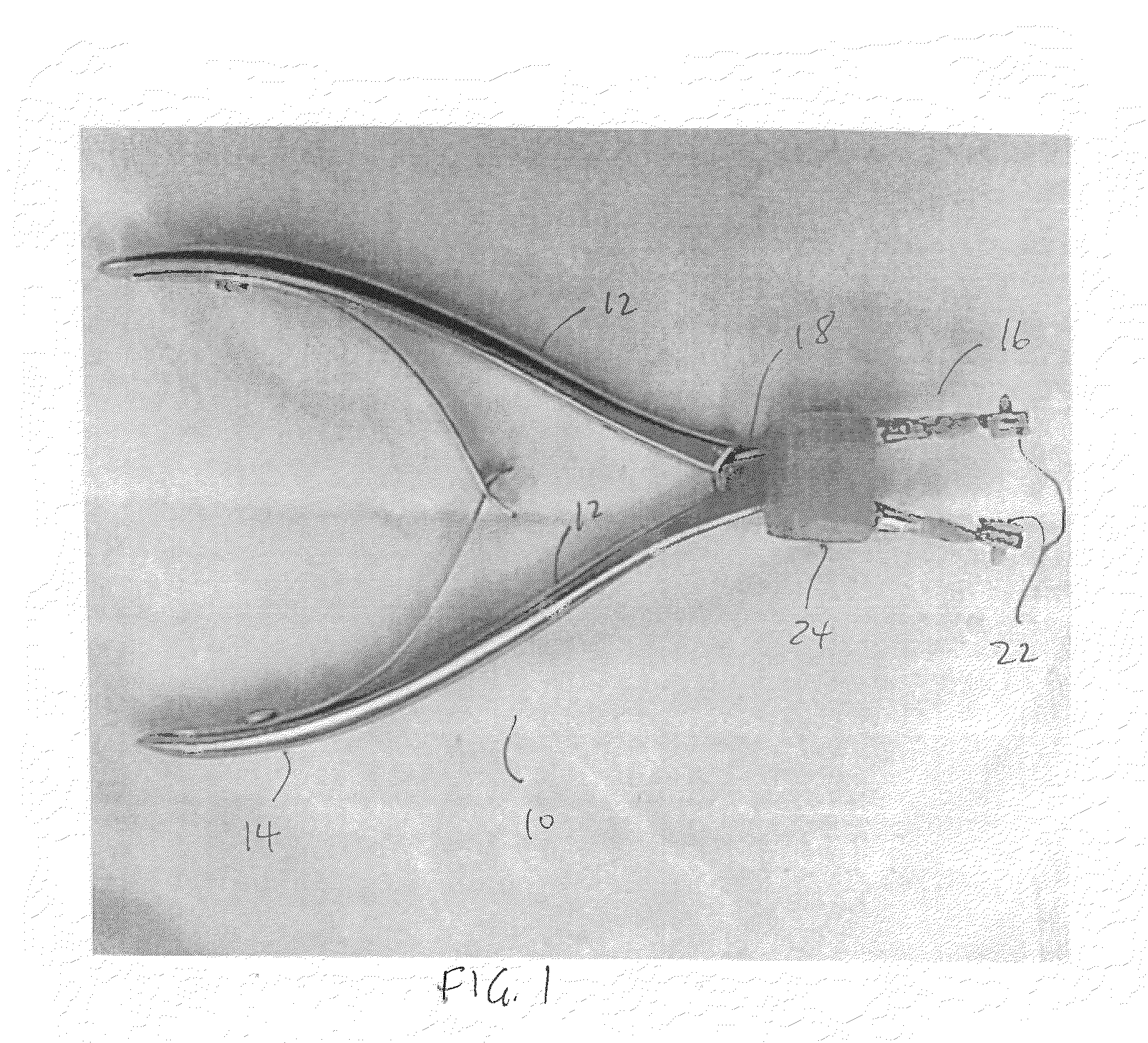
[0025]In one embodiment, as shown in FIGS. 1 and 2, the forceps (10) of the invention comprises a pair of forcep arms (12) each comprising a handle end (14) and a gripping end (16). The arms (12) are pivotally connected at a point (18) intermediate their ends (14, 16).

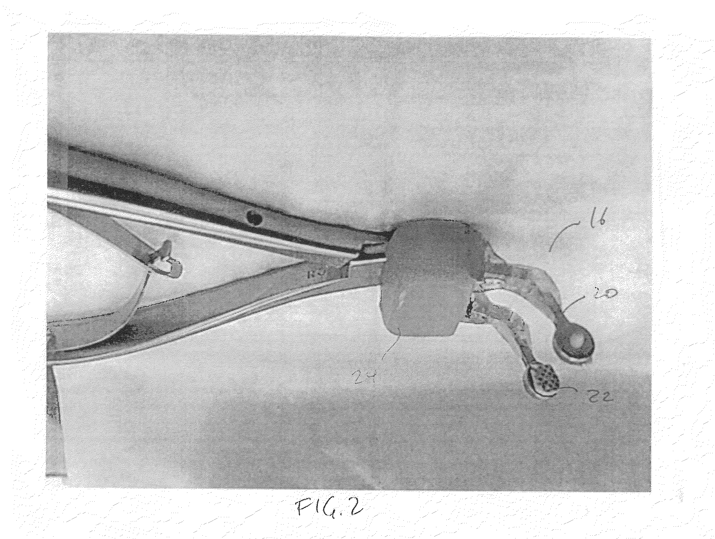
[0026]Referring to FIG. 2, each gripping end (16) comprises a gripping arm (20), such that the forceps (10) comprises two opposing gripping surfaces (22). The distance between the gripping surfaces (22) may be varied by pivotally adjusting the forcep arms (12). In one embodiment, as shown in FIG. 1, the gripping surfaces (22) may be biased away from each other by spring members between the handle end (14). A fulcrum pad (24) is provided intermediate the gripping end (16) and the handle end (14).

[0027]Although the forceps (1...


PUM


Abstract

Dental forceps include opposing gripping surfaces configured to grip a tooth or crown and a fulcrum pad adjacent the gripping surfaces. The forceps may act as a first class lever with the fulcrum pad to extract the tooth or crown when gripping the tooth or crown.

Description

CROSS REFERENCE TO RELATED APPLICATIONS[0001]This application claims the priority benefit of U.S. Provisional Application No. 61 / 813,513 filed on Apr. 18, 2013 entitled Improved Dental Forceps, the contents of which are incorporated herein by reference.FIELD OF THE INVENTION[0002]The present invention relates to an improved dental forceps tool.BACKGROUND TO THE INVENTION[0003]Significant advances have been made in the last few decades in dental care and treatment. Not only are there a host of personal dental care appliances and cleaning agents, but significant advances have also been made in the general practice and general dentistry field. It has become a common practice to repair missing teeth by placing a root form dental implant into the bone and restoring a crown on top of it. The dental implant is placed into the bone surgically. The patient may wait several months depending on bone quality for osseointegration of the implant to occur. A prosthetic abutment is then connected t...

Claims


Application Information

Patent Timeline
Patent Type & Authority Applications(United States)
IPC IPC(8): A61C3/16A61C3/14
CPCA61C3/14A61C3/162
Inventor CHANG, KIMSONG, JUN SUK
Owner CHANG KIM
Why Eureka
Try Eureka