Pressure integrity testing system

a technology of integrity testing and pressure, applied in the field of annular barrier systems, can solve the problems of affecting the integrity of the seal, and the operator cannot prove the control of the seal well,

Active Publication Date: 2014-10-30
WELLTEC OILFIELD SOLUTIONS AG
View PDF4 Cites 30 Cited by
  • Summary
  • Abstract
  • Description
  • Claims
  • Application Information

AI Technical Summary

Benefits of technology

[0004]It is an object of the present invention to wholly or partly overcome the above disadvantages and drawbacks of the prior art. More specifically, it is an object to provide an improved annular packer system which can be leak-tested without at the same time breaking the pressure integrity.

Problems solved by technology

If the pressure integrity is broken, the operator can no longer prove well control, and the well is shut down.
However, it is very difficult to leak-test the packer without at the same time breaking the pressure integrity, as the formation or cement is on one side, and thus, injection of a tracer into the formation fluid will break the integrity since the casing is then also penetrated.

Method used


Image

  • Pressure integrity testing system
  • Pressure integrity testing system
  • Pressure integrity testing system

Examples


Embodiment Construction

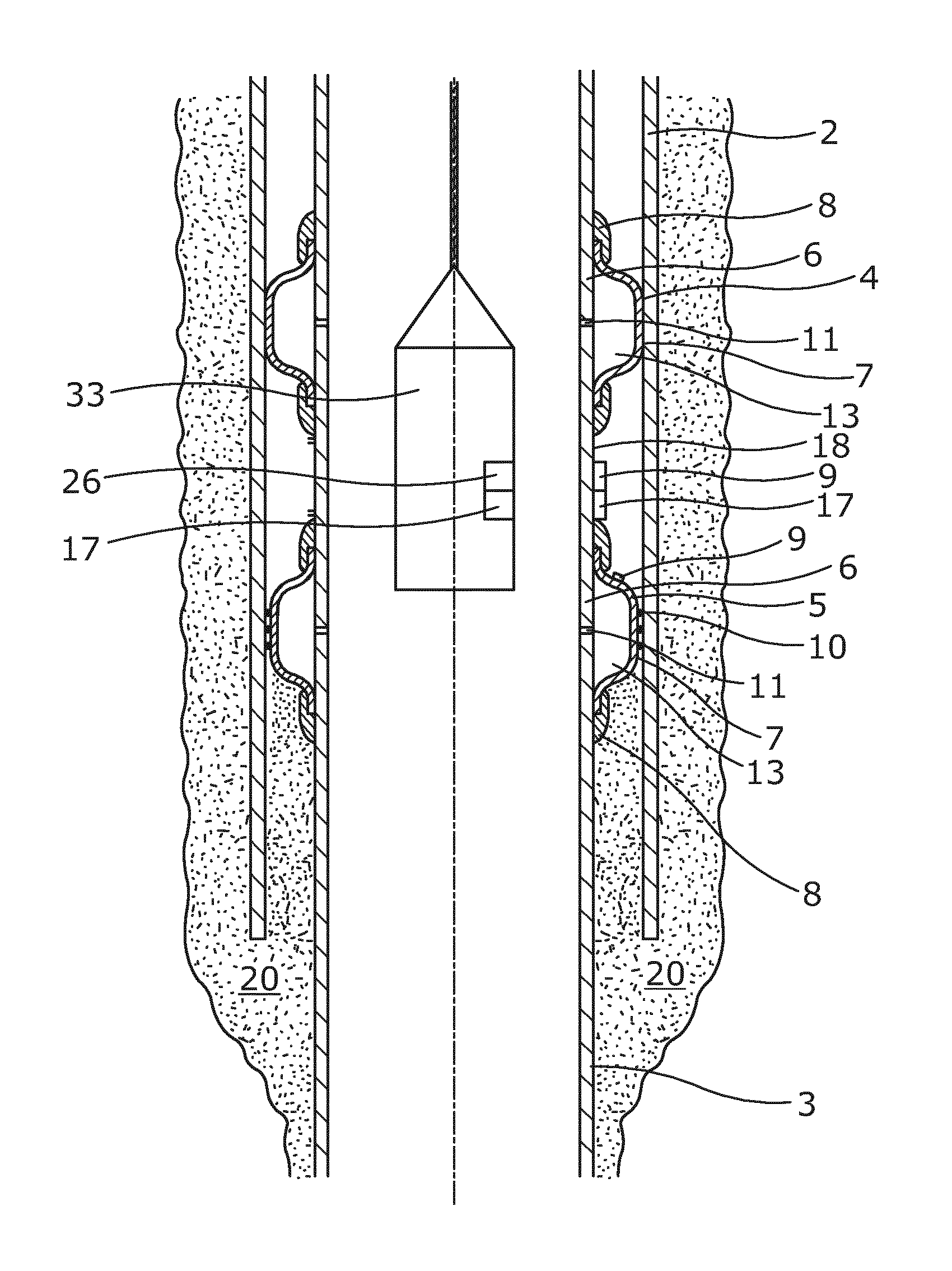
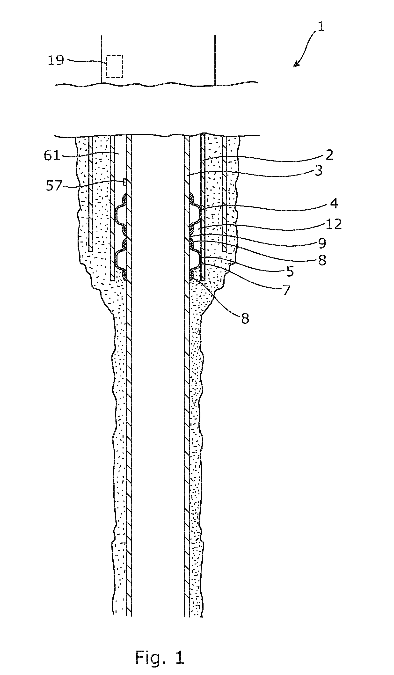
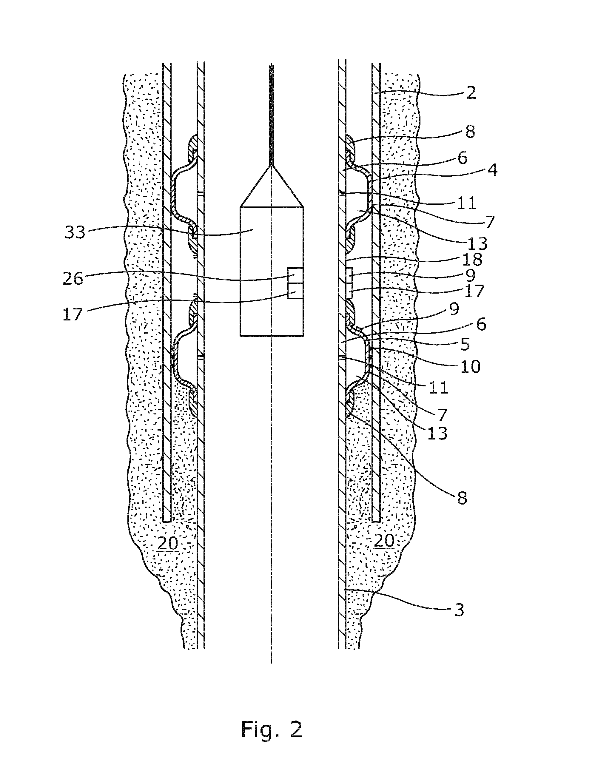
[0080]FIG. 1 shows an annular barrier system 1 for proving a testable annular barrier arranged between a first metal casing 2 and a second metal casing 3. The annular barrier system 1 comprises a first annular barrier 4 and a second annular barrier 5 arranged spaced apart. As shown in FIG. 2, each barrier comprises a tubular part 6 and an expandable sleeve 7 made of metal surrounding the tubular part 6 and being connected with the tubular part, the expandable sleeve 7 defining a barrier space 13, and the annular barriers 4, 5 further comprise a first fluid passage 11 for letting fluid into the barrier space 13 to expand the metal sleeve 7. The tubular part 6 extends in a longitudinal direction for mounting as part of the second metal casing 3, and the annular barriers 4, 5 are arranged adjacent to each other. When the expandable sleeves 7 are expanded to abut the first metal casing 2, the sleeves form an annular space 12 between the annular barriers, the first metal casing 2 and the...


PUM


Abstract

The present invention relates to an annular barrier system (1) for proving a testable annular barrier arranged between a first metal casing (2) or borehole and a second metal casing (3), the second metal casing having an outer face. The annular barrier system comprises a first annular barrier (4) and a second annular barrier (5), each barrier comprising a tubular part (6) made of metal extending in a longitudinal direction for mounting as part of the second metal casing, an expandable metal sleeve (7) surrounding and connected with the tubular part and defining an annular barrier space (13), and a first fluid passage (11) in the tubular part for letting fluid into the annular barrier space to expand the sleeve. The annular barrier system further comprises a sensor (9), and when the expandable sleeves are expanded to abut the first metal casing or borehole, a first annular space (12) is defined between the annular barriers, wherein the sensor is arranged to determine a condition of the annular space in order to test the isolation ability of at least one of the annular barriers. The present invention also relates to a method of testing pressure integrity of a well using an annular barrier system as described above.

Description

FIELD OF THE INVENTION[0001]The present invention relates to an annular barrier system for proving a testable annular barrier arranged between a first metal casing or borehole and a second metal casing, the second metal casing having an outer face. The present invention also relates to a method of testing pressure integrity of a well using an annular barrier system as described above.BACKGROUND ART[0002]When arranging an intermediate casing in a conductor pipe, or when arranging a production casing in an intermediate casing, an annular isolation packer is set in the annular space to prevent the fluid from the surrounding formation from flowing into the annular space. The pressure integrity between two tubulars is very important and the annulus between them is tested on a regular basis. If the pressure integrity is broken, the operator can no longer prove well control, and the well is shut down.[0003]Therefore, it is very important that these annular packers seal off the formation pr...

Claims


Application Information

Patent Timeline
Patent Type & Authority Applications(United States)
IPC IPC(8): E21B47/00
CPCE21B47/0006E21B33/1243E21B47/06E21B47/10E21B33/12E21B47/007
Inventor HALLUNDB.AE BUTTED.K, JORGENHAZEL, PAUL
Owner WELLTEC OILFIELD SOLUTIONS AG
Why Eureka
Try Eureka