RF induction lamp with ferrite isolation system

Inactive Publication Date: 2014-10-30
LUCIDITY LIGHTS
View PDF6 Cites 18 Cited by
  • Summary
  • Abstract
  • Description
  • Claims
  • Application Information

AI Technical Summary

Benefits of technology

[0018]In embodiments, it may be desirable to connect the power coupler of the induction lamp to RF ground through a capacitor that has low impedance at the operating frequency of the lamp, but high impedance at the frequenc

Problems solved by technology

Use of electrodes creates certain problems.
In the case of fluorescent lamps, this leads to long, thin lamps, which are ideal for lighting office ceilings, but are not a good fit for lamps designed to replace conventional incandescent lamps.
A plastic cover shaped like a conventional incandescent lamp is sometimes placed over the bent tubes to provide a more attractive shape, but these covers absorb light, making the lamp less efficient.
Bent and spiral tube lamps also have wasted space between the tubes, making them larger than necessary.
The use of electrodes creates problems other than shape and size.
Electrodes will wear out quickly if the lamp is turned on and off many times, as it would be in a residential bathroom and similar applications.
While this is not a concern with typical fluorescent lamps, it can be a problem with other types of discharge lamps.
The lower operating f

Method used


Image

  • RF induction lamp with ferrite isolation system
  • RF induction lamp with ferrite isolation system
  • RF induction lamp with ferrite isolation system

Examples


Example

[0043]While described in connection with certain exemplary and non-limiting embodiments, other exemplary embodiments would be understood by one of ordinary skill in the art and are encompassed herein. It is therefore understood that, as used herein, all references to an “embodiment” or “embodiments” refer to an exemplary and non-limiting embodiment or embodiments, respectively.

DETAILED DESCRIPTION

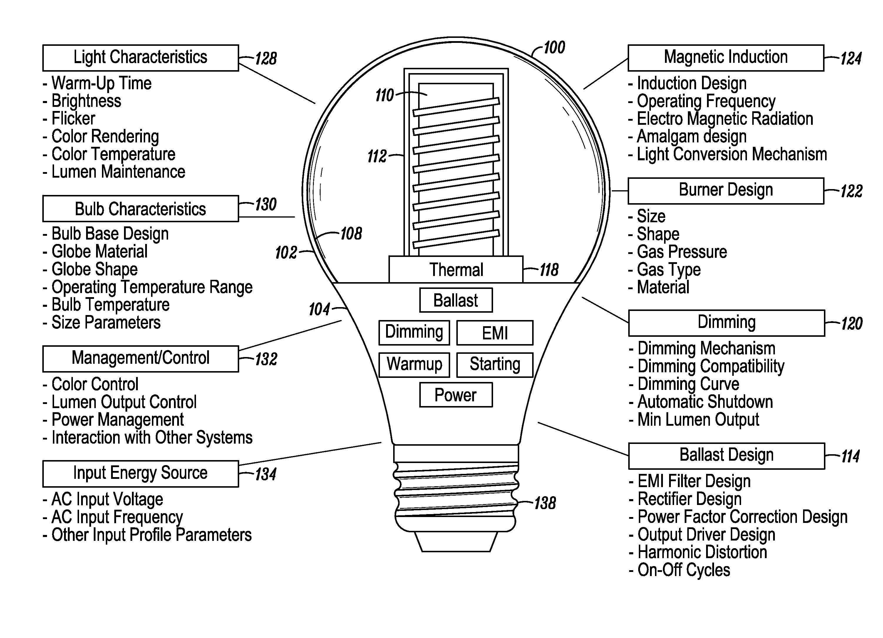
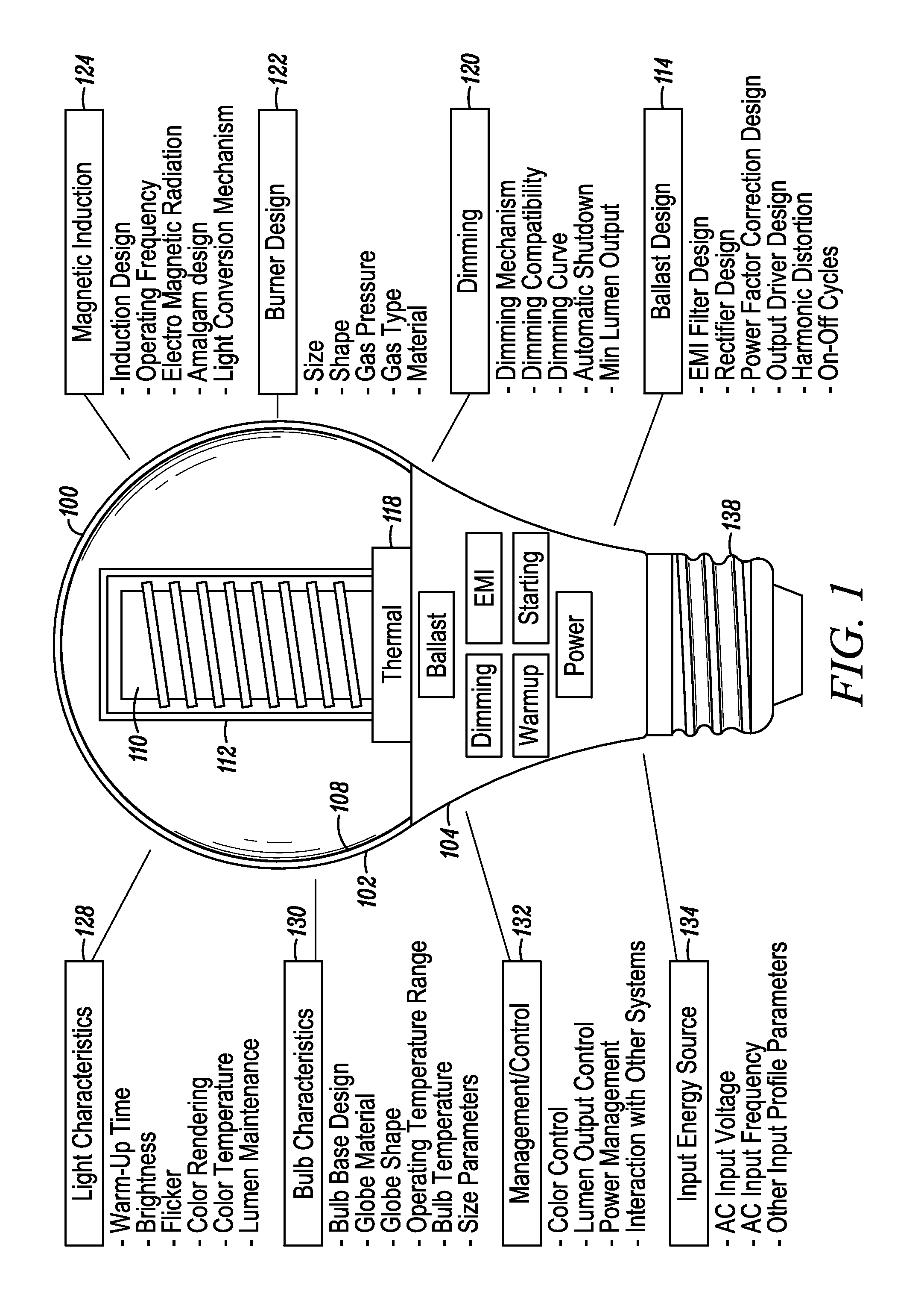
[0044]An induction-driven electrodeless discharge lamp, here after referred to as an ‘induction lamp’, excites a gas within a lamp envelope through an electric field created by a time-varying magnetic field rather than through electrically conductive connections (such as electrodes) that physically protrude into the envelope. Since the electrodes are a limiting factor in the life of a lamp, eliminating them potentially extends the life that may be expected from the light source. In addition, because there are no metallic electrodes within the envelope, the burner design may employ higher ef...


PUM


Abstract

An induction RF fluorescent lamp includes a lamp envelope with a re-entrant cavity both covered on a partial vacuum side with phosphor and filled with a working gas mixture; a power coupler on the non-vacuum side of said re-entrant cavity comprising a ferromagnetic core overwound with at least one turn of an electrical conductor; an electronic ballast, wherein the ballast converts mains frequency voltage and current to a power coupler frequency voltage and current, the electronic ballast providing the voltage and current to the power coupler through at least two of a plurality of electrical terminals of the electronic ballast; a capacitor electrically connected between the ferromagnetic core and at least one of the plurality of electrical terminals of the electronic ballast, wherein the magnitude of the impedance of the capacitor is high at the mains frequency and the magnitude of the impedance of that same capacitor is low at the operating frequency of the RF fluorescent lamp.

Description

BACKGROUND[0001]1. Field[0002]The present invention generally relates to induction lamps, and more specifically to reducing a shock hazard associated with EMI reduction schemes.[0003]2. Description of Related Art[0004]Discharge lamps create light by exciting an electrical discharge in a gas and using that discharge to create visible light in various ways. In the case of fluorescent lamps the gas is typically a mixture of argon, krypton and / or neon, plus a small amount of mercury. Other types of discharge lamps may use other gasses. The gas is contained in a partially evacuated transparent virtuous envelope called a bulb or arc tube depending upon the type of lamp.[0005]In conventional lamps electrically conductive electrodes mounted inside the bulb or arc tube along with the gas provide the electric field used to drive the discharge.[0006]Use of electrodes creates certain problems. First, the discharge has to be designed to have a relatively high voltage in order to minimize loses a...

Claims


Application Information

Patent Timeline
IPC IPC(8): H01J65/04
CPCH01J65/048H01J61/56
Inventor ROBERTS, VICTOR D.
Owner LUCIDITY LIGHTS
Why Eureka
Try Eureka