Substrate treatment apparatus
- Summary
- Abstract
- Description
- Claims
- Application Information
AI Technical Summary
Benefits of technology
Problems solved by technology
Method used
Image
Examples
first embodiment
(Substrate Treatment Apparatus )
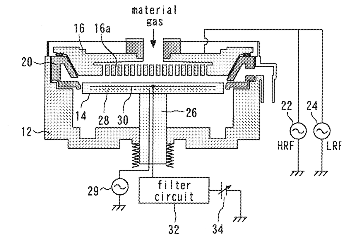
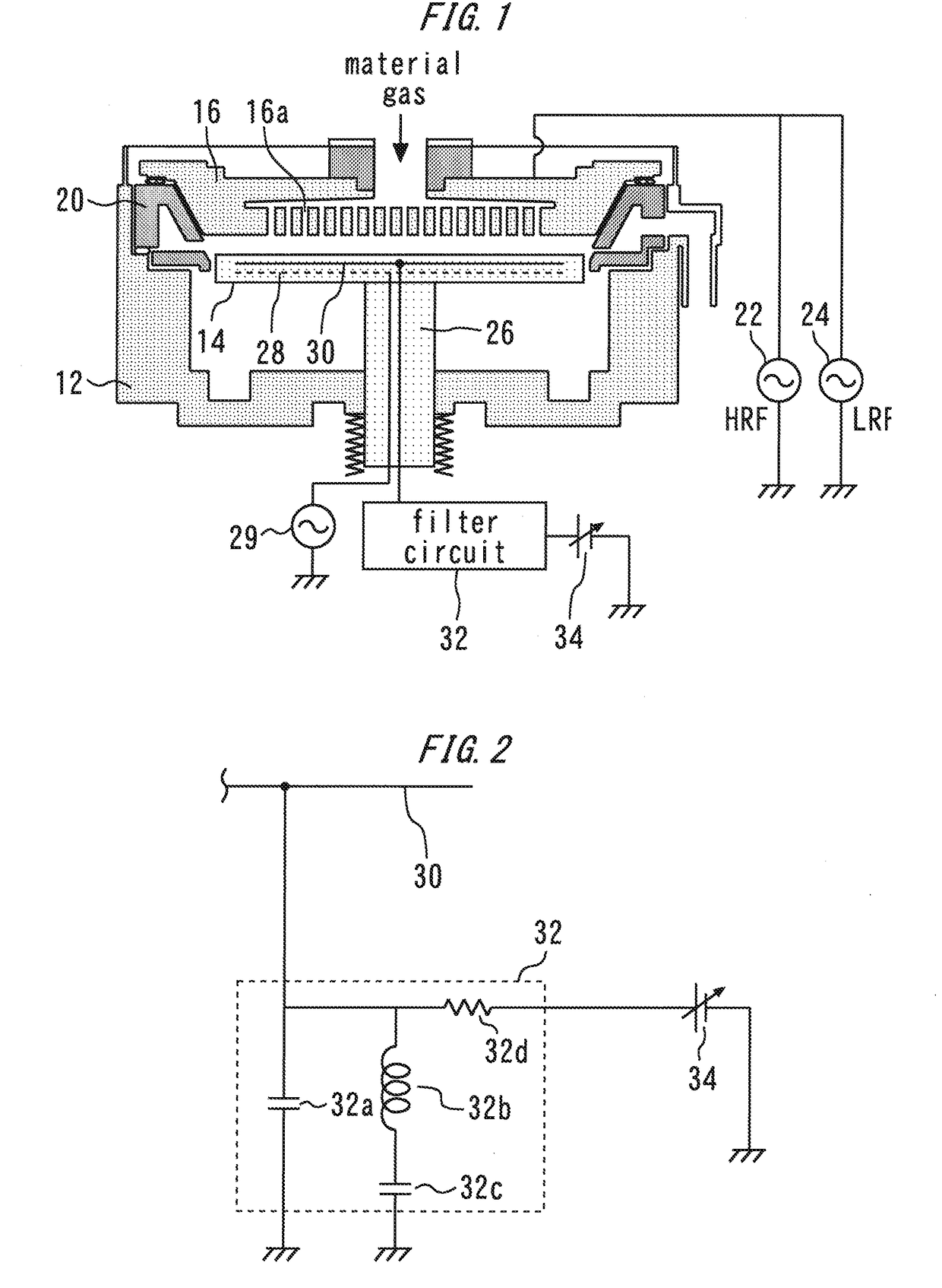
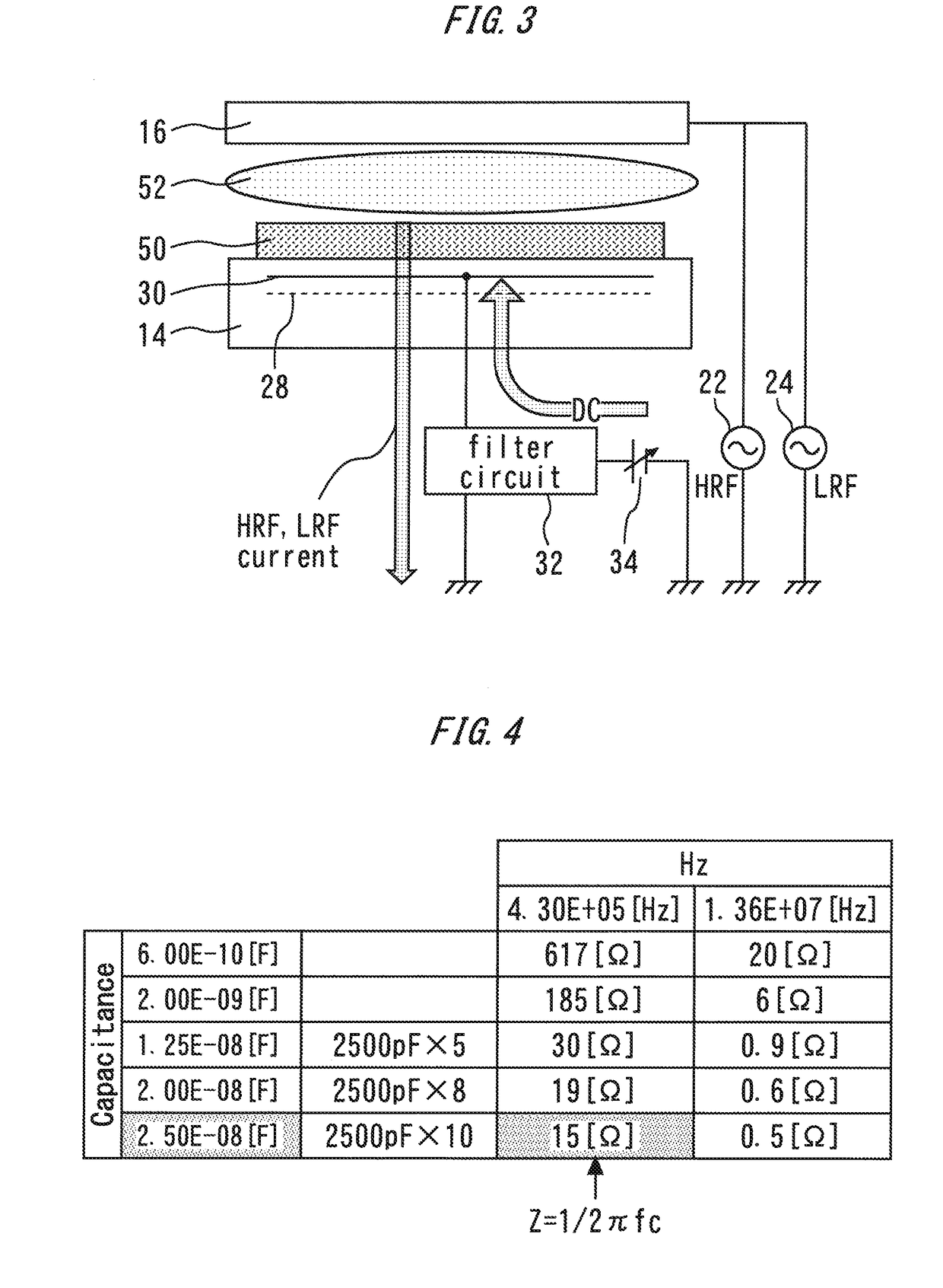
[0030]The first embodiment of the present invention provides the filter circuit capable of passing AC power at HRF and LRF to the ground. Therefore, it is possible to provide the filter circuit 32 that functions as a filter that grounds the AC power at the first frequency and the AC power at the second frequency without increasing the size of the capacitor as in the case of the comparative example. By providing the filter circuit 32, it is possible to normally generate discharge between the upper electrode 16 and the lower electrode 14 and also protect the DC power supply 34 provided for an electrostatic chuck from AC power.
(Modification)
[0031]The substrate treatment apparatus according to the first embodiment of the present invention can be modified in various ways without losing its features. By providing the capacitor 32a as the first filter circuit, it is possible to pass AC power at the first frequency at, for example, approximately 13.56 MHz in ...
second embodiment
[0033]FIG. 5 is a diagram illustrating a filter circuit 70 of a substrate treatment apparatus according to a second embodiment. The filter circuit 70 is provided with a third filter circuit composed of a parallel circuit of a capacitor 32e and an inductor 32f The third filter circuit is provided between the internal electrode 30 and the DC power supply 34 by avoiding a path connecting the internal electrode 30 and the capacitor 32a which is the first filter circuit. That is, the third filter circuit is connected to a wiring which is branched from the wiring that connects the internal electrode 30 and the capacitor 32a.
[0034]The third filter circuit is formed so as to become low impedance with respect to AC power at the second frequency and become high impedance with respect to AC power at the first frequency. That is, the third filter circuit functions as a high-cut filter. Suppose a case where a capacitance of the capacitor 32e is 100 pF and an inductance L of the inductor 32f is ...
third embodiment
[0036]FIG. 6 is a diagram illustrating a substrate treatment apparatus according to a third embodiment. An AC power supply 80 supplies AC power to the internal electrode 16b of the upper electrode 16. The DC power supply 34 is connected to the internal electrode 30 via the filter circuit 32. The internal electrode 30 is provided in the lower electrode 14. The DC power supply 34 applies a voltage to the internal electrode 30, and thereby provides an electrostatic chuck.
[0037]A switch 82 can switch connection or disconnection between the internal electrode 30 and the ground. The switch 82 connects the internal electrode 30 to the ground for a period during which treatment is applied to the substrate and keeps the internal electrode 30 disconnected from the ground for other periods. Therefore, the period during which plasma is generated and treatment is applied to the substrate, AC power applied to the upper electrode 16 flows to the ground via both the filter circuit 32 and the switch...
PUM
| Property | Measurement | Unit |
|---|---|---|
| Frequency | aaaaa | aaaaa |
| Frequency | aaaaa | aaaaa |
| Frequency | aaaaa | aaaaa |
Abstract
Description
Claims
Application Information
 - R&D
- Intellectual Property
- Life Sciences
- Materials
- Tech Scout
- Unparalleled Data Quality
- Higher Quality Content
- 60% Fewer Hallucinations
Browse by: Latest US Patents, China's latest patents, Technical Efficacy Thesaurus, Application Domain, Technology Topic, Popular Technical Reports.
© 2025 PatSnap. All rights reserved.Legal|Privacy policy|Modern Slavery Act Transparency Statement|Sitemap|About US| Contact US: help@patsnap.com


