Low impedance probe structure and purpose

A low-impedance, probe-based technology, which is applied to components of electrical measuring instruments, measuring devices, instruments, etc., can solve problems such as uneven electroplating metal layers, increased production costs, and unstable welding.

Inactive Publication Date: 2004-12-29
SHANGHAI FEILIWEIER METALLIC WIRE
View PDF0 Cites 7 Cited by
  • Summary
  • Abstract
  • Description
  • Claims
  • Application Information

AI Technical Summary

Problems solved by technology

[0002] As we all know, the probe structure has quite a variety of forms, such as figure 1 As shown, referring to the probe structure 10, there is an integrally formed sleeve 100, the sleeve 100 is an open end 102 entering the inner wall of the sleeve 100, the inner wall of the sleeve 100 is coated with a metal layer, and then a compression spring 101 And a needle portion 103 is inserted into an actuating space 110 of the sleeve 100 through the open end 102. Because the existing probe structure 10 has only one open end 102, the electroplated metal layer is accumulated at the bottom of the sleeve 100, so it is easy to cause electroplated metal layer inhomogeneity, which results in high resistance
[0003] The above-mentioned traditional probe structure 10 is transmitted to the printed circuit board (PCB) 105 by the needle part 103 through the compression spring 101, and finally passes through the sleeve 100 to form a three-piece structure during telecommunication transmission, because the needle part 103, The compression spring 101 and the sleeve 100 are an independent component respectively, so the more components passed through during telecommunication transmission, the resistance generated will be relatively increased, which will affect the quality of telecommunication transmission; and the traditional probe structure 10 and the sleeve 100 are all gold-plated , when

Method used


Image

  • Low impedance probe structure and purpose
  • Low impedance probe structure and purpose
  • Low impedance probe structure and purpose

Examples


Embodiment Construction

[0042] The present invention is easy to implement for the professional people, and in conjunction with accompanying drawing the present invention is described in detail as follows:

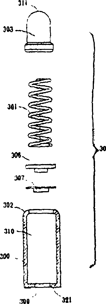
[0043] image 3 The shown probe structure of the present invention includes:

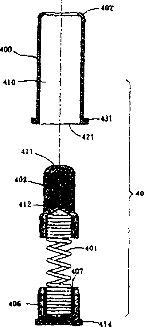
[0044] A gold-plated sleeve 400 is a hollow circular tube with two ends open, one end is a retracted inner side 402, the other end is provided with a stop side 421, and a convex portion extending from the stop side 421 to both sides 431, and an action space 410 between the stopper 402 and the retracted side 421;

[0045] Put a gold-plated needle 403 into the retracted side 402 from the stop side 421 to expose the gold-plated needle 403, and put a gold-plated spring 401 into an actuation space 410 from the stop side 421, and finally place the seat 406 by The stop side 421 is plugged in so that the stop side 421 is closed, thereby constituting the probe structure of the present invention.

[0046] Among them, the gold-...


PUM


Abstract

The low impedance probe structure is used mainly for signal transmission of printed circuit board. The present invention includes gold plating sleeve, needle part, spring and tin plating seat. The hollow sleeve has two opened ends, including one for setting the needle part and the other for setting the seat, and hollow part for the spring to be set in. The spring is soldered to the seat so as to reduce resistance during electric signal transmission and to constitute one low impedance probe structure. The bottom of the sleeve with combined seat is designed as stepped to increase the soldered area between the probe structure and printed circuit board and raise soldering stability.

Description

[technical field] [0001] The invention relates to a low-impedance probe structure, in particular to a low-impedance probe structure and application for lowering resistance to provide a better telecommunication transmission. [technical background] [0002] As we all know, the probe structure has quite a variety of forms, such as figure 1 As shown, referring to the probe structure 10, there is an integrally formed sleeve 100, the sleeve 100 is an open end 102 entering the inner wall of the sleeve 100, the inner wall of the sleeve 100 is coated with a metal layer, and then a compression spring 101 And a needle portion 103 is inserted into an actuating space 110 of the sleeve 100 through the open end 102. Because the existing probe structure 10 has only one open end 102, the electroplated metal layer is accumulated at the bottom of the sleeve 100, so it is easy to cause electroplated metal Layer inhomogeneity, resulting in high resistance. [0003] The above-mentioned traditio...

Claims


Application Information

Patent Timeline
IPC IPC(8): G01R1/067H01R12/71
Inventor 李锦松
Owner SHANGHAI FEILIWEIER METALLIC WIRE
Why Eureka
Try Eureka