
Pallet assembly

a technology of pallets and assembly parts, applied in the field of pallets, can solve the problems of other physical properties of pallets to decrease, strength, toughness and stiffness, and achieve the effect of improving fire retardant properties and increasing the performance of the upper deck

Active Publication Date: 2016-09-27
REHRIG PACIFIC CO INC
View PDF19 Cites 21 Cited by
  • Summary
  • Abstract
  • Description
  • Claims
  • Application Information

AI Technical Summary

Benefits of technology

[0003]A pallet according to one embodiment of the present invention includes a deck supported at a distance above the floor by a plurality of columns. The deck includes a plurality of ribs extending downwardly from an upper sheet. A reinforcement sheet is secured to lower ends of the ribs. The reinforcement sheet may be a plurality of coextruded sheets, one having a first material selected to bond well with the ribs and at least one other sheet of a second material selected for other improved physical properties. In one example disclosed herein, the second material is chosen for improved fire retardant properties. As one example, the reinforcement sheet can be vibration welded to the lower ends of the ribs, thereby providing a strong weld between the reinforcement sheet and the ribs. The reinforcement sheet provides increased performance of the upper deck while the fire retardant layer of the reinforcement sheet provides fire retardant properties to one of the largest surfaces on the pallet.

Problems solved by technology

However, these additives can cause other physical properties of the pallet to decrease, such as strength, toughness and stiffness.

Method used


Image

  • Pallet assembly
  • Pallet assembly
  • Pallet assembly

Examples


Embodiment Construction

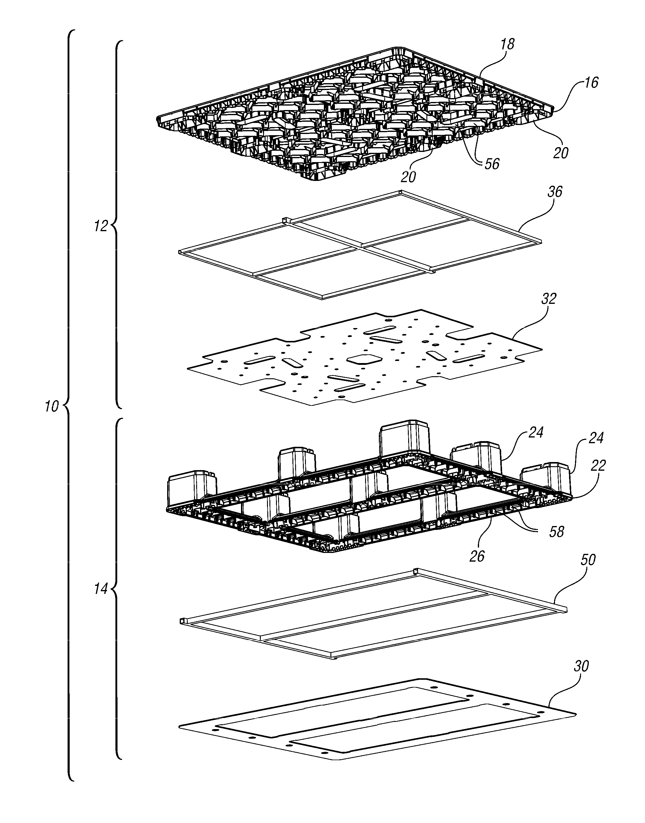
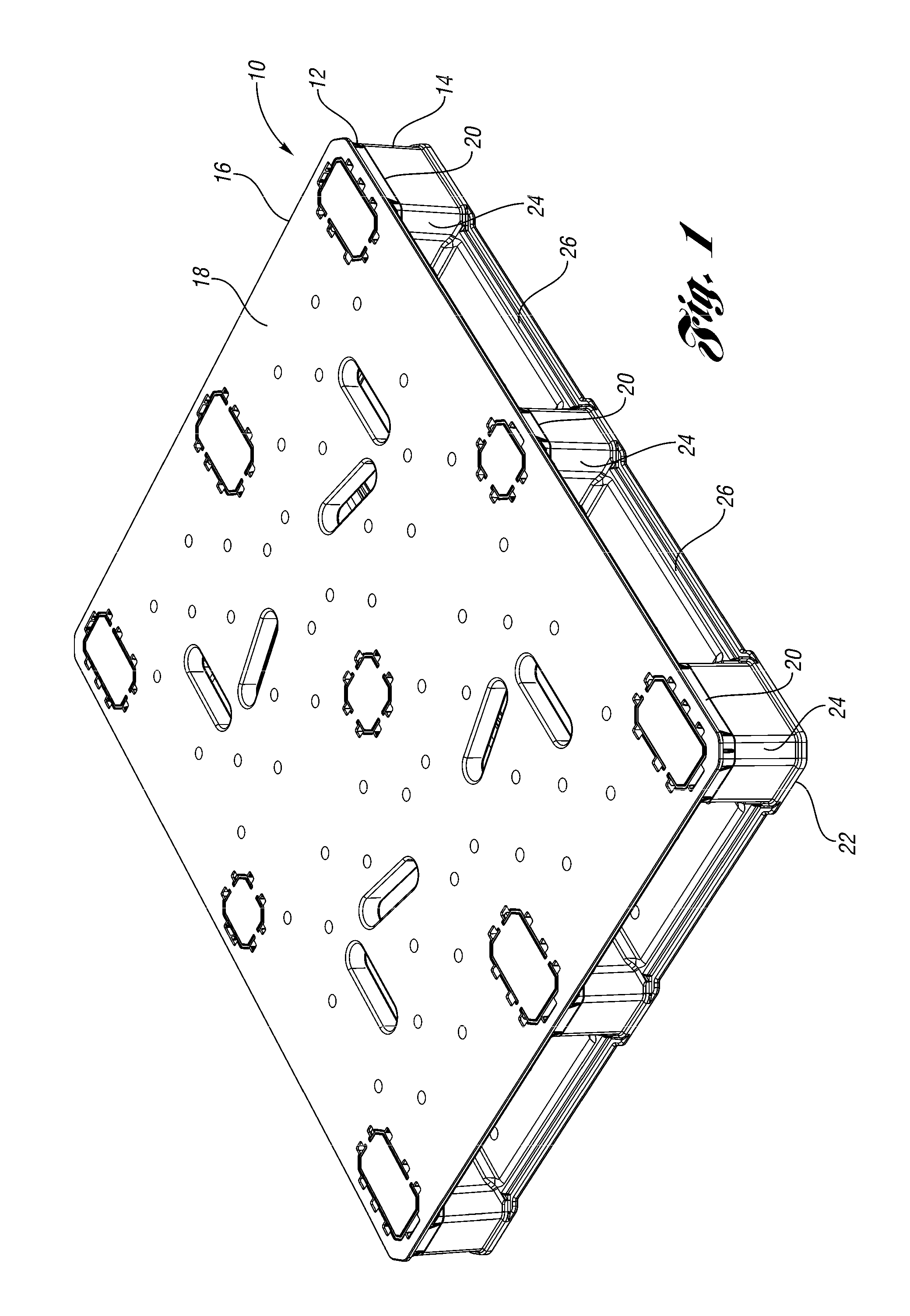
[0019]A pallet assembly 10 according to one embodiment of the present invention is shown in FIG. 1. The pallet 10 generally includes an upper structure 12 and a lower structure 14. The upper structure 12 includes an upper deck 16 having a generally planar upper support surface 18 and a plurality of column connectors 20 protruding downwardly therefrom. The lower structure 14 includes an integrally molded lower portion 22 including a plurality of columns 24 with runners 26 extending therebetween.

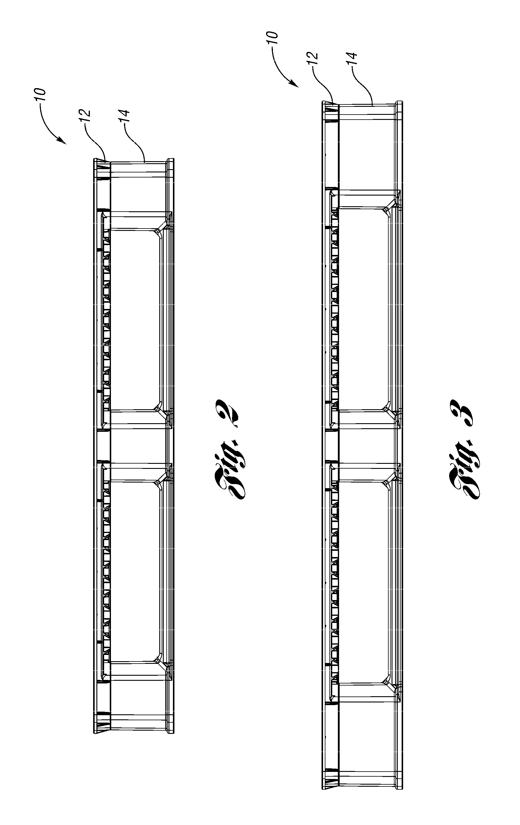
[0020]FIGS. 2 and 3 are front and side views of the pallet assembly 10. FIG. 4 is a top view of the pallet assembly 10.

[0021]FIG. 5 is a bottom view of the pallet assembly 10. As shown, the lower structure 14 includes a lower reinforcement sheet 30, shaped to align with the runners 26 and the columns 24. The upper structure 12 includes an upper reinforcement sheet 32 secured to the bottom thereof.

[0022]An exploded view of the pallet assembly 10 is shown in FIG. 6. The upper structure 12 includ...


PUM

PropertyMeasurementUnit
fire retardant propertiesaaaaaaaaaa
structureaaaaaaaaaa
resistance to fireaaaaaaaaaa

Abstract

A pallet includes a deck having columns supporting the deck. The deck includes a plurality of ribs extending downwardly from an upper sheet. A reinforcement sheet is secured to lower ends of the ribs. The reinforcement sheet is a coextruded sheet having a first material selected to bond well with the ribs and a second material selected for other improved physical properties. In the example disclosed herein, the second material is chosen for improved fire retardant properties. As one example, the reinforcement sheet can be vibration welded or hot plate welded to the lower ends of the ribs, thereby providing a strong weld between the reinforcement sheet and the ribs, which provides increased performance of the upper deck while the fire retardant layer of the reinforcement sheet provides fire retardant properties to one of the largest surfaces on the pallet.

Description

BACKGROUND OF THE INVENTION[0001]The present invention relates generally to pallets. Pallets generally include an upper deck having columns below to support goods thereon above the floor. The columns also provide openings below the deck for the tines of a forklift.[0002]It has been proposed to add additives to the material of the pallet in order to improve its resistance to fire. However, these additives can cause other physical properties of the pallet to decrease, such as strength, toughness and stiffness.SUMMARY OF THE INVENTION[0003]A pallet according to one embodiment of the present invention includes a deck supported at a distance above the floor by a plurality of columns. The deck includes a plurality of ribs extending downwardly from an upper sheet. A reinforcement sheet is secured to lower ends of the ribs. The reinforcement sheet may be a plurality of coextruded sheets, one having a first material selected to bond well with the ribs and at least one other sheet of a second...

Claims


Application Information

Patent Timeline
Patent Type & Authority Patents(United States)
IPC IPC(8): B65D19/38B65D19/00B29C45/00
CPCB65D19/0016B29C45/0003B65D19/0073B65D2519/00034B65D2519/00044B65D2519/00069B65D2519/00079B65D2519/0086B65D2519/00104B65D2519/00139B65D2519/00273B65D2519/00293B65D2519/00323B65D2519/00333B65D2519/00407B65D2519/00412B65D2519/00437B65D2519/00442B65D2519/00562B65D2519/00567
Inventor APPS, WILLIAM P.
Owner REHRIG PACIFIC CO INC
Learn More