Doorbell system with energy storage device

Active Publication Date: 2020-12-10
LOGITECH EURO SA
View PDF0 Cites 6 Cited by
  • Summary
  • Abstract
  • Description
  • Claims
  • Application Information

AI Technical Summary

Benefits of technology

[0005]In some embodiments, a power supply in a doorbell system includes a doorbell button and a boost rectifier circuit including a plurality of active devices configured in a bridge circuit topology. In response to the doorbell button (e.g., switch) being deactivated, the boost rectifier circuit can be configured to: receive an alternating current (AC) input voltage, simultaneously rectify and boost the AC input voltage thereby generating a direct current (DC) output voltage with a higher voltage amplitude th

Problems solved by technology

Despite the many advances, many contemporary systems that enhance existing doorbell implementations (e.g., adding video capability) need cumbersome add-on supplementary circuitry that is often subject to significant

Method used


Image

  • Doorbell system with energy storage device
  • Doorbell system with energy storage device
  • Doorbell system with energy storage device

Examples


Embodiment Construction

[0058]Embodiments of this invention are generally directed to electronic systems. More specifically, some embodiments relate to an improved doorbell system using boost rectification to improve power consumption characteristics for a wide variety of supplementary doorbell system modifications, additions, and other system enhancing applications.

[0059]In the following description, for the purpose of explanation, numerous examples and details are set forth in order to provide an understanding of embodiments of the present invention. It will be evident, however, to one skilled in the art that certain embodiments can be practiced without some of these details, or with modifications or equivalents thereof.

Doorbell with Boost Circuit

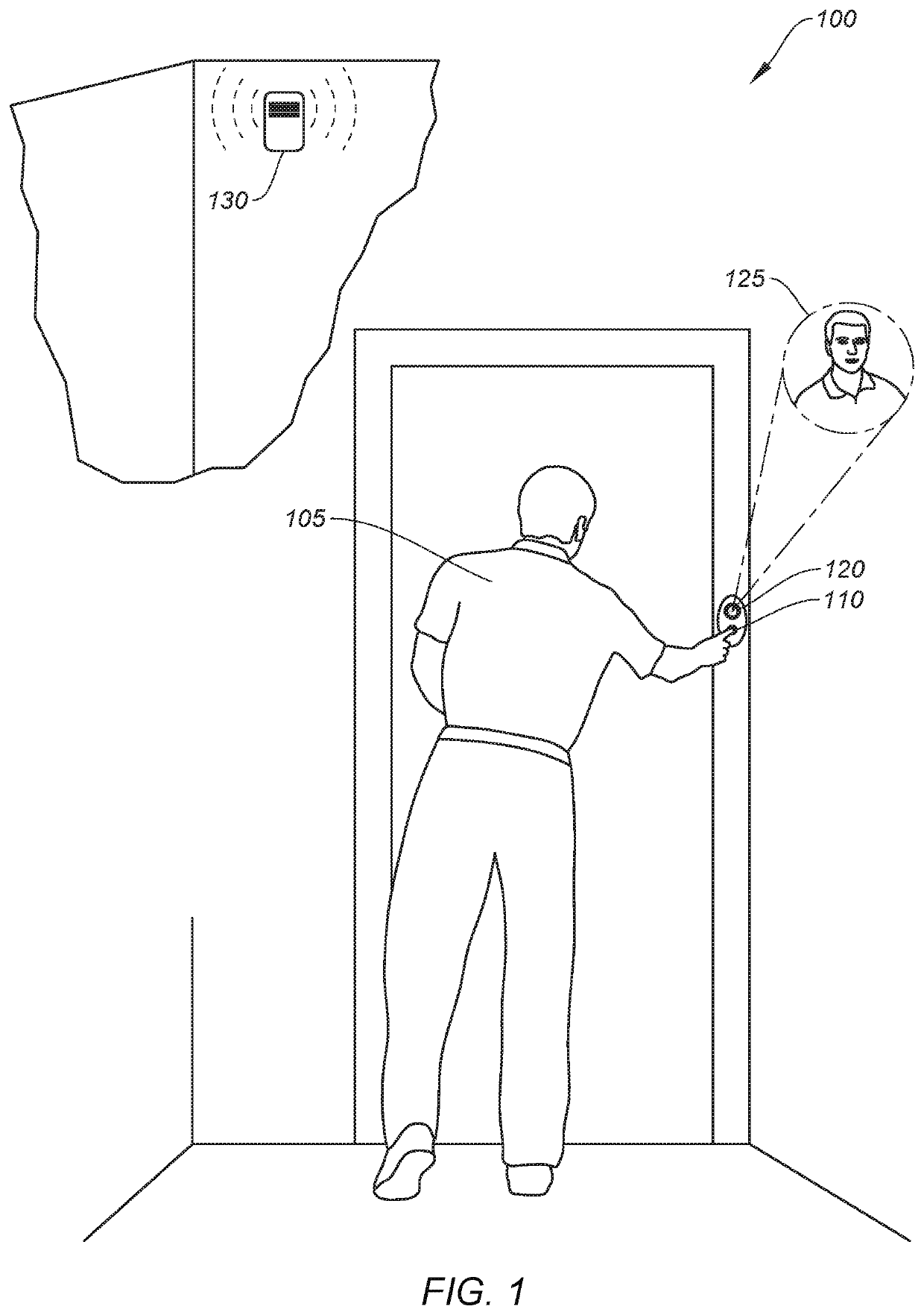
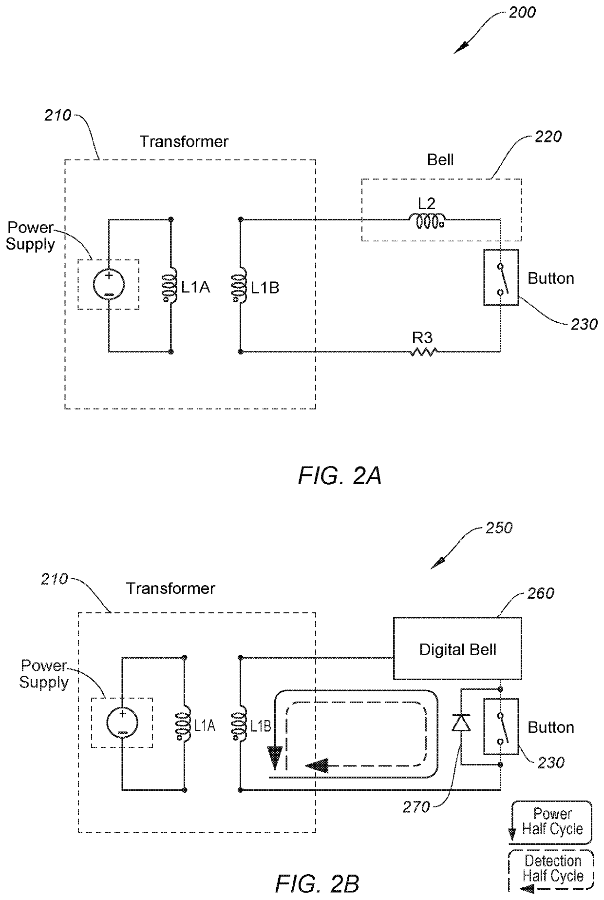
[0060]Aspects of the invention relate to a novel boost rectifier circuit that can be incorporated into an existing conventional doorbell system in a “plug and play” fashion, such that no additional modifications or complicated installations are required. A user ...


PUM


Abstract

In some embodiments, a video doorbell system includes a video doorbell device on an exterior surface of a structure and a chime kit within an interior of the structure. A transformer can be coupled in-series via electrical conductors with the video doorbell device and the chime kit. The chime kit can include an energy storage device that is charged via the electrical conductors. When a user activates a button on the video doorbell device power control circuitry within the video doorbell device can transmit a signal on the electrical conductors. Button detection circuitry within the chime kit can detect the signal and respond by transferring power from the energy storage device to a chime. While the chime is activated the transformer can continuously supply the video doorbell device with power.

Description

CROSS-REFERENCES TO RELATED APPLICATIONS[0001]This application is related to co-owned U.S. Non-provisional application Ser. No. 16 / 024,586, filed on Jun. 29, 2018, titled “DOORBELL SYSTEM WITH PULSE-DRIVEN BOOST RECTIFIER,” issued as U.S. Pat. No. 10,311,685, which is hereby incorporated by reference in its entirety for all purposes.BACKGROUND[0002]A doorbell is typically configured as a signaling device placed near a door to a building's entrance that, when activated, alerts an occupant to the presence of a visitor. Doorbells have existed for over 200 years with early versions using mechanical actuators (e.g., pull cords) to strike a bell plate, and later commercially available models (circa 1900) using electrical systems with chimes, bells, or buzzers. Conventional electrically controlled doorbell systems with mechanical chimes have changed little over the years and still exist in many households today.[0003]There have been many technological advances in doorbell systems since the...

Claims


Application Information

Patent Timeline
IPC IPC(8): G08B3/10H04N7/18H02M7/219
CPCH02J7/00G08B3/10H02M7/219H04N7/186H02M1/44G08B13/196H02J50/001H02J2207/50H02M1/0085H02J7/34
Inventor ROSENBERG, ARONLONG, JOHN M.STOUGHTON, NICK
Owner LOGITECH EURO SA
Why Eureka
Try Eureka