Liquid Crystal Display and Narrow Bezel Structure Thereof

a liquid crystal display and narrow bezel technology, applied in non-linear optics, instruments, optics, etc., can solve the problem that the narrow bezel lcd module cannot meet the demand for a variety of overall appearances, and achieve the effect of improving the front cover structur

Active Publication Date: 2014-11-06
TCL CHINA STAR OPTOELECTRONICS TECH CO LTD
View PDF1 Cites 9 Cited by
  • Summary
  • Abstract
  • Description
  • Claims
  • Application Information

AI Technical Summary

Benefits of technology

[0025]In contrast to the prior art, the present invention provides a LCD having an improved front cover structure that is cleverly butt jointed to the polarizer film. Hence, the visual effect of no front cover is achieved. Moreover, the added outer side cover further maintains the close attachment of the front cover to the liquid crystal module. Or, locking members are utilized to fix the liquid crystal module so as to guarantee the LCD is installed firmly and safely.

Problems solved by technology

Hence the overall design idea still lies in the side cover 3, and the prior art ultra-narrow bezel LCD module can not satisfy the demand for a variety of overall appearances.

Method used


Image

  • Liquid Crystal Display and Narrow Bezel Structure Thereof
  • Liquid Crystal Display and Narrow Bezel Structure Thereof
  • Liquid Crystal Display and Narrow Bezel Structure Thereof

Examples


embodiment 1

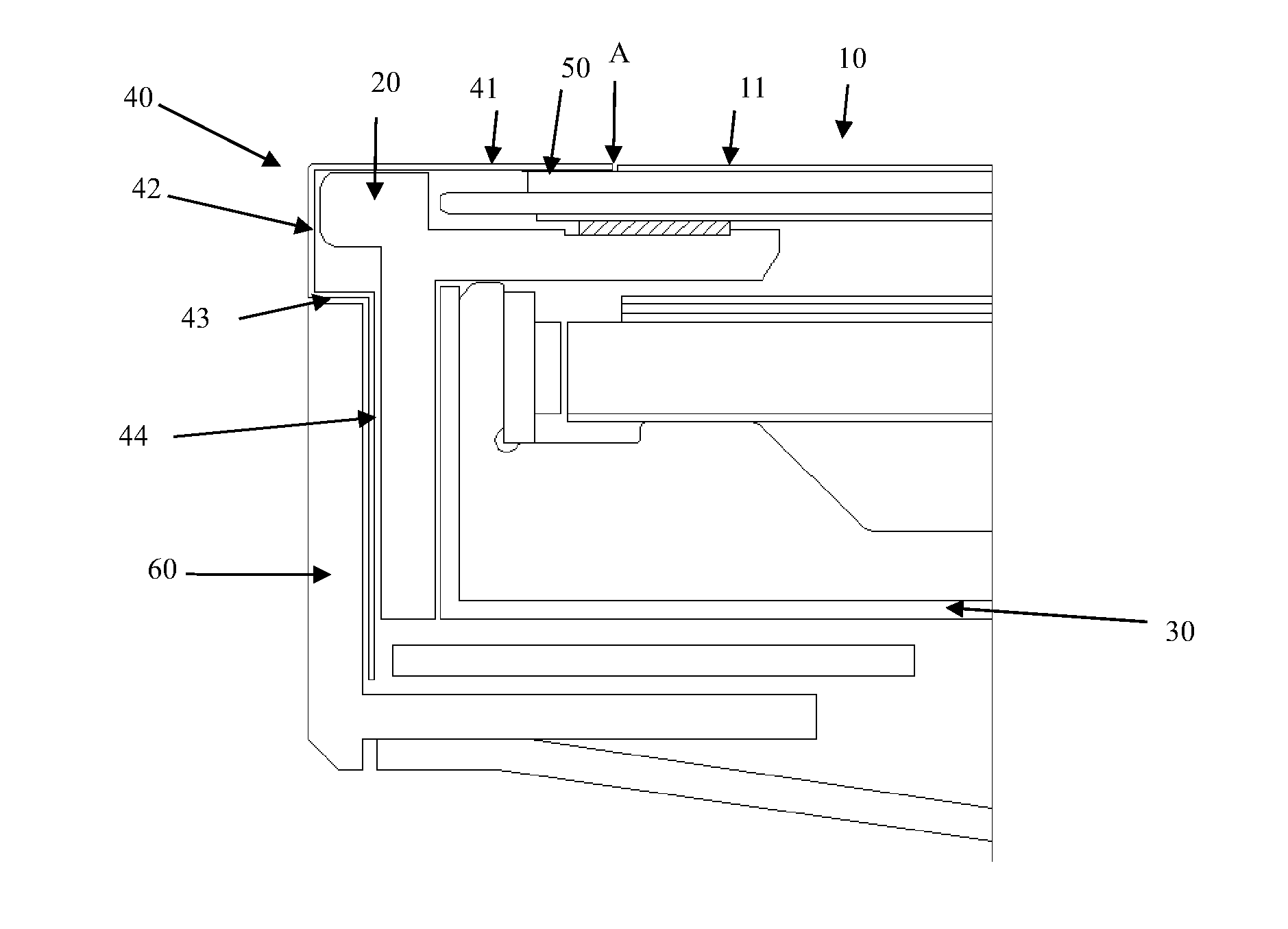
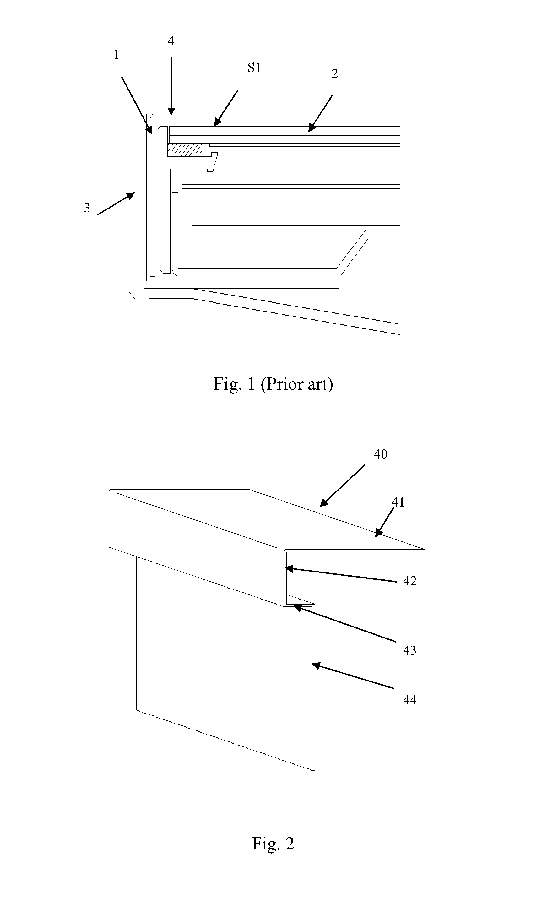
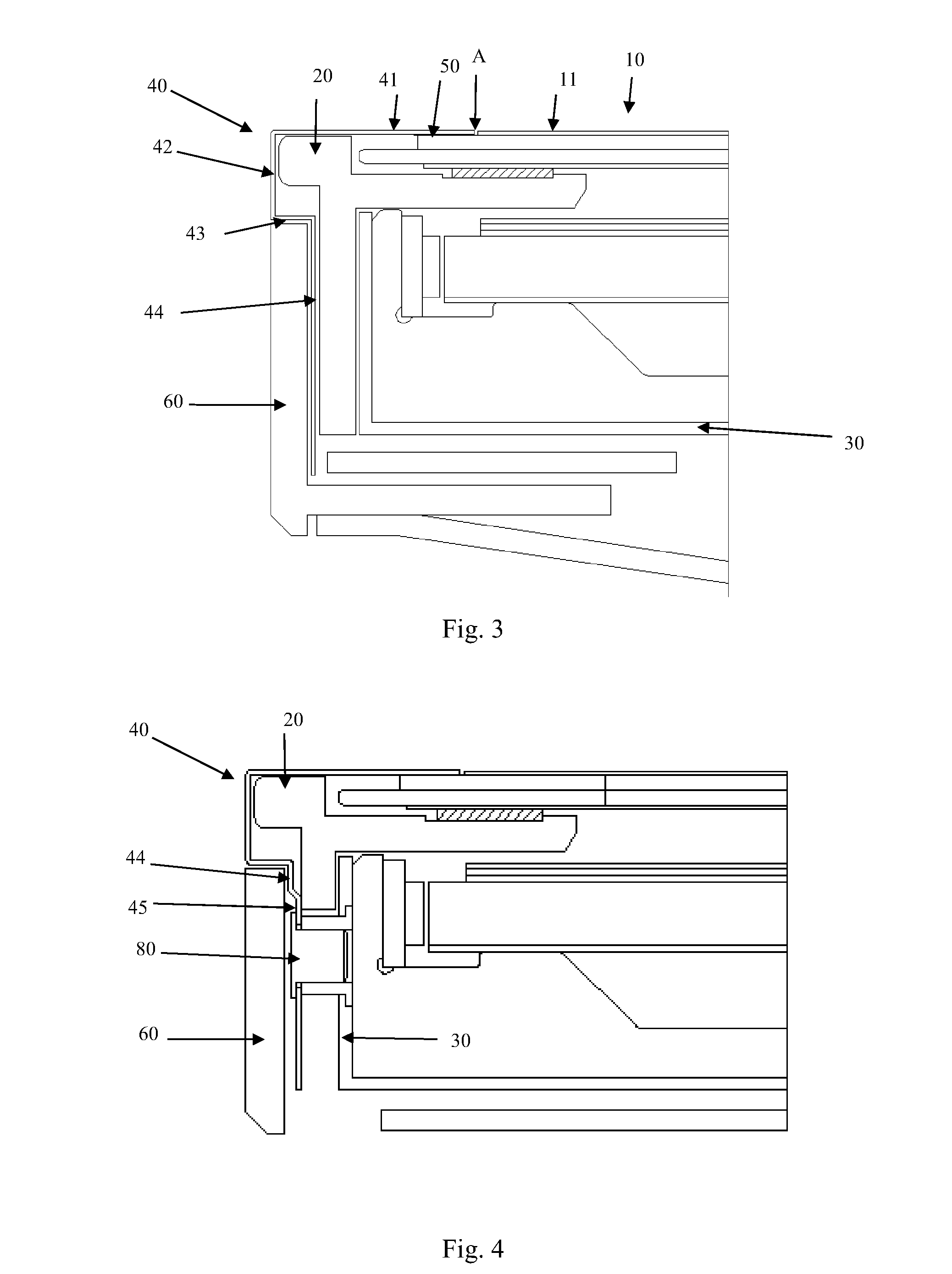
[0034]As shown in FIG. 2 and FIG. 3, a narrow bezel structure of a LCD comprises a liquid crystal module 10, a middle cover 20, a back cover 30, and a front cover 40. An external layer of the liquid crystal module 10 is a polarizer film 11 and the polarizer film 11 is spaced apart from an edge of the liquid crystal module 10 to form a step. The present invention differs from the prior art in that the front cover 40 comprises a first horizontal part 41, a first perpendicular part 42, a second horizontal part 43, and a second perpendicular part 44 which are integrally formed and sequentially connected. The first horizontal part 41 is attached to the step. The second horizontal part 43 and the second perpendicular part 44 form a second step, and the second perpendicular part 44 is fixedly connected to the back cover 30. Please refer to FIG. 2, a bottom of the first horizontal part 41 is stuck to the liquid crystal module 10 through a double-sided tape 50. One end of the first horizonta...

embodiment 2

[0036]Please refer to FIG. 5, FIG. 6, and FIG. 7, locking members 70 are utilized to enhance the fixed effect of the liquid crystal module 10 according to the present embodiment. A number of locking members 70 distributed in the liquid crystal module 10 are used for holding the liquid crystal module 10. The locking member 70 comprises a horizontal part 71 and a perpendicular part 72 perpendicularly connected to the horizontal part 71. The horizontal part 71 presses an upper surface 12 of a bottom glass substrate in an outer lead bonding (OLB) area of the liquid crystal module 10. The perpendicular part 72 and the middle cover 20 are connected by a snap-fit assembly correspondingly disposed on them. A thickness of the horizontal part 71 must not exceed a thickness of a top glass substrate 14 of the liquid crystal module 10. A buffer material layer 13 is optionally attached to a bottom surface of the horizontal part 71. The snap-fit assembly comprises an undercut 73 disposed in the pe...


PUM

PropertyMeasurementUnit
thicknessaaaaaaaaaa
thicknessaaaaaaaaaa
thicknessaaaaaaaaaa

Abstract

A narrow bezel structure of a LCD is disclosed. The narrow bezel structure of the LCD comprises a liquid crystal module, a front cover, a middle cover, and a back cover. An external layer of the liquid crystal module is a polarizer film, and the polarizer film is spaced apart from an edge of the liquid crystal module to form a step. The front cover comprises a first horizontal part, a first perpendicular part, a second horizontal part, and a second perpendicular part that are integrally formed and sequentially connected. The first horizontal part is attached to the step. The second horizontal part and the second perpendicular part form a second step. The second perpendicular part is fixedly connected to the back cover. The present invention further provides a LCD utilizing the narrow bezel structure.

Description

BACKGROUND OF THE INVENTION[0001]1. Field of the Invention[0002]The present invention relates to a liquid crystal display (LCD) technology, more particularly, to a narrow bezel LCD.[0003]2. Description of the Related Art[0004]The basic structure of a prior art LCD is as shown in FIG. 1. A front cover 1 is mainly used for pressing a liquid crystal module 2 so as to prevent the liquid crystal module 2 from separating. With the development of display technology, a width 4 of the front cover 1, which is the width 4 of the front cover 1 on the same lateral side as the liquid crystal module 2, becomes smaller and smaller. However, the front cover 1 must have a certain thickness to maintain its rigidity. Such a thickness is typically between 0.4 and 1 mm. The visual appearance is that the front cover 1 protrudes from a display surface S1 of the liquid crystal module 2 to negatively influence the aesthetic feeling of appearance.[0005]The trend of the liquid crystal display module (LCD modul...

Claims


Application Information

Patent Timeline
Patent Type & Authority Applications(United States)
IPC IPC(8): G02F1/1333
CPCG02F1/133308G02F1/133314G02F1/13332G02F1/133608
Inventor TANG, GUOFU
Owner TCL CHINA STAR OPTOELECTRONICS TECH CO LTD
Why Eureka
Try Eureka