
Apparatus for retina phototherapy

a retina and apparatus technology, applied in the field of apparatus for retina phototherapy, can solve the problems of patients' cramped or close quarters, inability to use prior art systems and devices, and inability to effectively target and treat patients' retinas

Inactive Publication Date: 2014-11-06
OJAI RETINAL TECH
View PDF1 Cites 16 Cited by
  • Summary
  • Abstract
  • Description
  • Claims
  • Application Information

AI Technical Summary

Benefits of technology

The present invention is about an apparatus for retina phototherapy. The apparatus includes a retina phototherapy device that can be adjusted in relation to a headrest assembly. It comprises a radiant energy source and projection optics that can target the retina of an individual using the headrest assembly. The apparatus also has a camera that can capture the image of the retina and display it on a monitor. The base of the retina phototherapy device can be adjusted in a three-dimensional coordinate space using a joystick. The camera can capture an infrared image of the retina and the source and optics can be focused using the joystick. The technical effects of the invention include providing a precise and efficient tool for retina phototherapy.

Problems solved by technology

Prior art systems and devices were not comfortable for patients to use and were inefficient at targeting and treating patient's retinas.
Such prior art systems presented cramped or close quarters for patients to squeeze or jam themselves into.
Such could cause pain or discomfort for the patient.
In certain instances, it may also result in injury if the patient cannot maintain the position or falls out of position either to the floor or into a piece of furniture or equipment.
In such uncomfortable positions, it was difficult for a patient to remain sufficiently immobile long enough for a treatment cycle to complete.

Method used


Image

  • Apparatus for retina phototherapy
  • Apparatus for retina phototherapy
  • Apparatus for retina phototherapy

Examples


Embodiment Construction

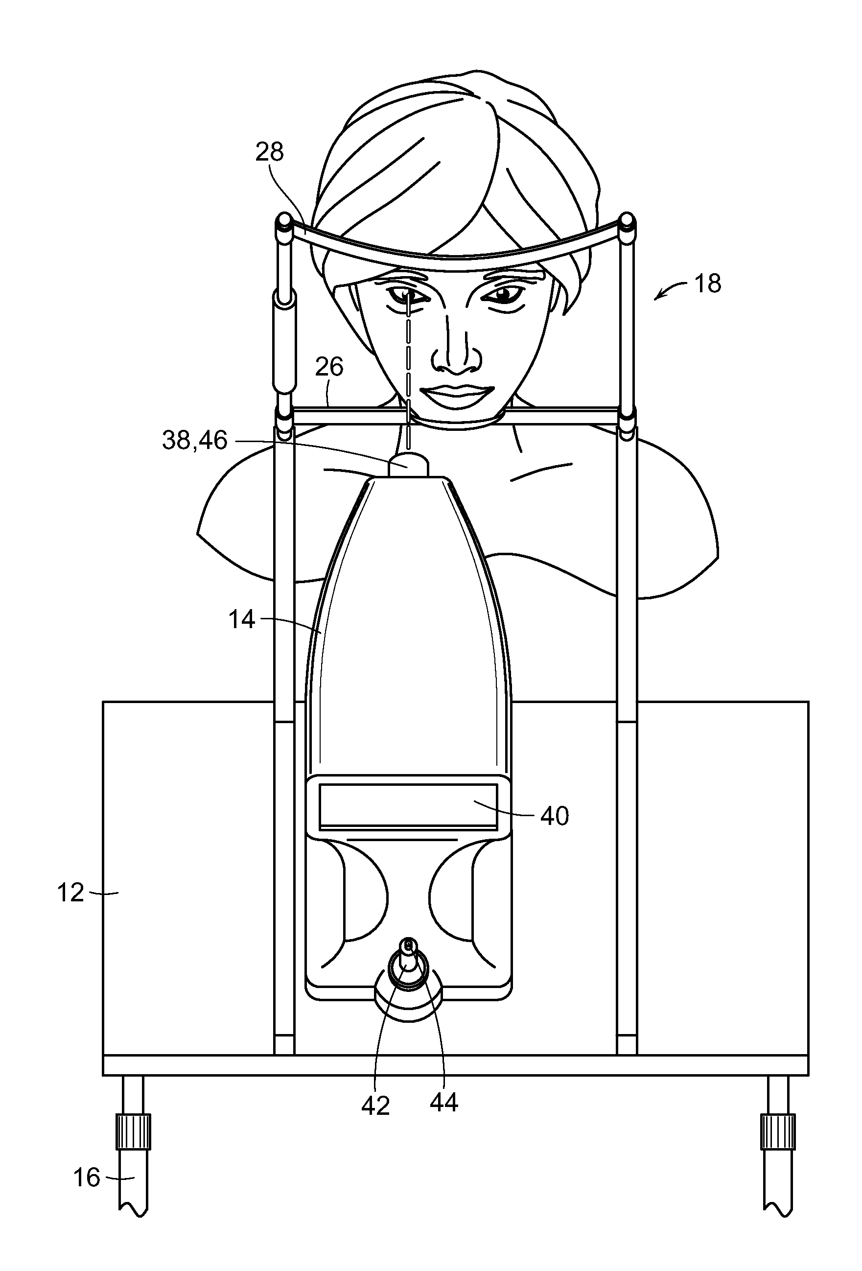
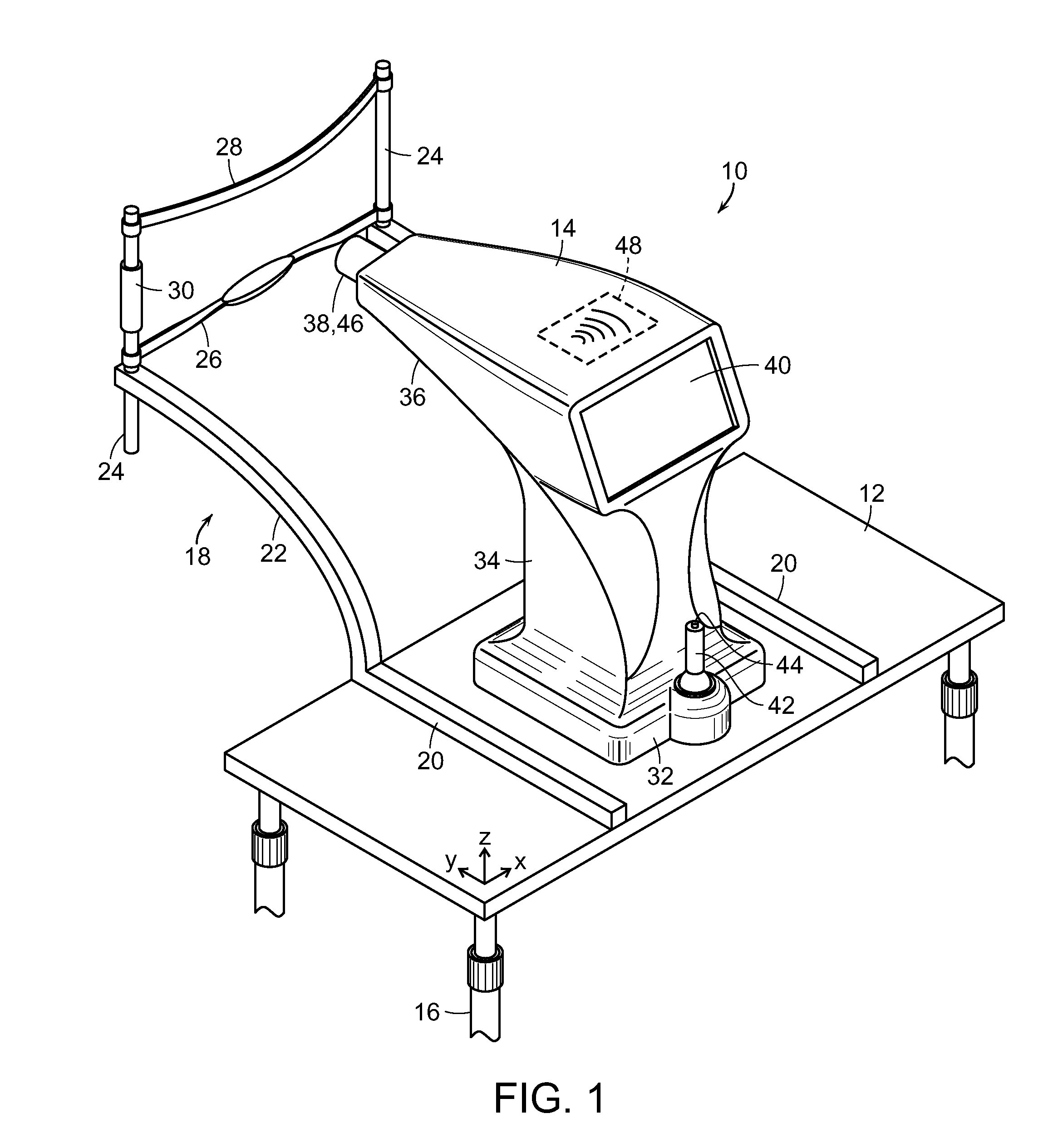
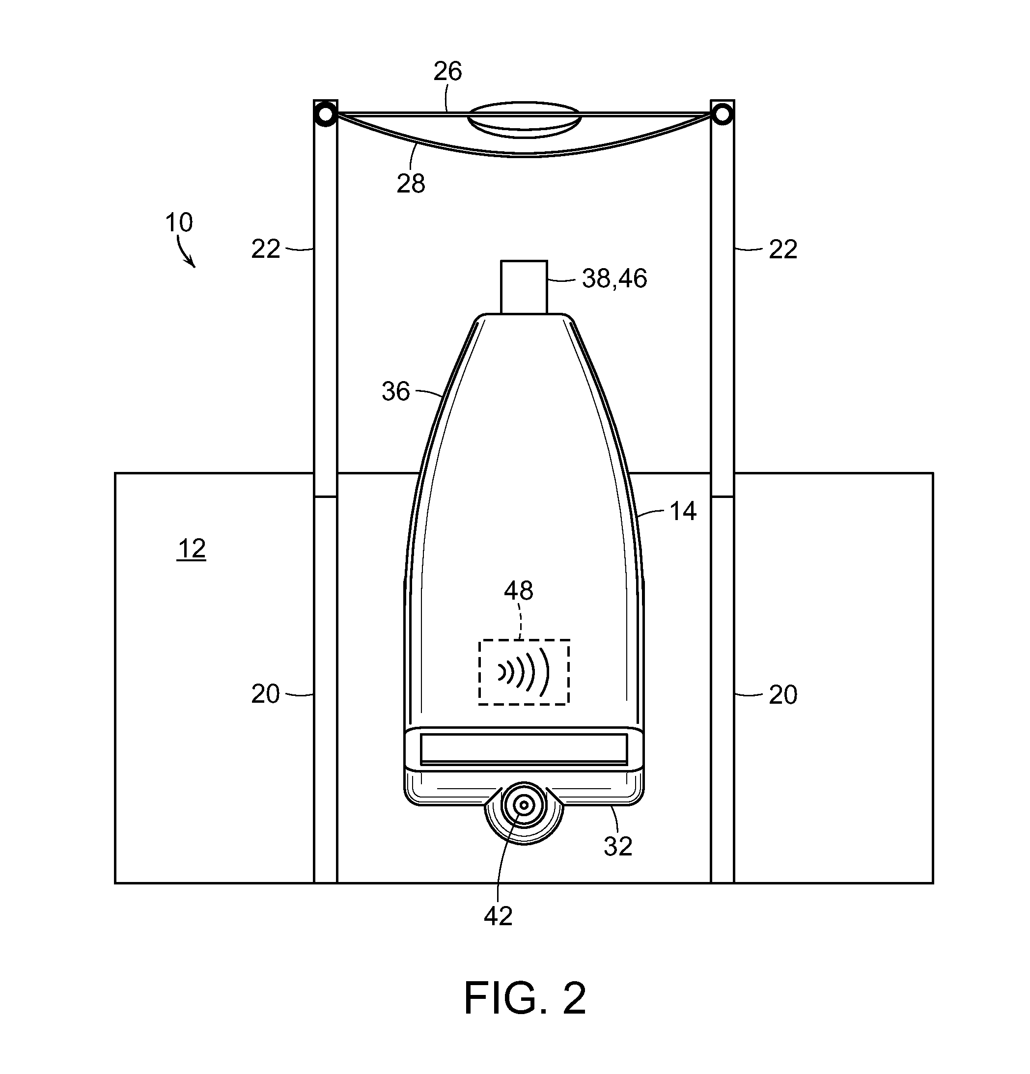
[0019]The present invention is generally directed to a system for treating a patient's retina with a radiant energy source, including but not limited to a laser. Throughout this description the use of “laser” on its own or as part of a larger assembly shall include any radiant energy source. The system, generally referred to by reference numeral 10 in FIGS. 1-7, consists primarily of a working surface 12 and a retina phototherapy device 14. The following description will refer to the relative position of various components in a 3-dimensional coordinate system, i.e., X, Y, and Z axes. Under this convention, the X-axis refers to lateral or side-to-side movement relative to the horizontal. The Y-axis refers to longitudinal or front-to-back movement relative to the horizontal. The Z-axis refers to vertical or up-and-down movement relative to the horizontal.

[0020]As illustrated in FIGS. 1-5, the working surface 12 is a generally horizontal, planar surface that rests on legs 16 or similar...


PUM


Abstract

A retina phototherapy system having a substantially horizontal working surface with an adjustable, ergonomic headrest assembly. A retina phototherapy device is adjustably disposed on the working surface and generally includes laser optics, a camera, a flat screen monitor, and a control joystick. The laser optics are oriented generally in the direction of the headrest assembly and are configurable so as to focus on a retina of a person using the headrest assembly. The camera is generally coaxially disposed with the laser optics and connected to the monitor so as to project an image of the retina treatment area. The control joystick is configured to micro-adjust a position of the retina phototherapy device in relation to the working surface.

Description

RELATED APPLICATION[0001]This application is a continuation-in-part of U.S. application Ser. No. 13 / 798,523, filed on Mar. 13, 2013, which is a continuation-in-part of U.S. application Ser. No. 13 / 481,124, filed May 25, 2012.BACKGROUND OF THE INVENTION[0002]The present invention is generally directed to a system for reliably and comfortably providing retina treatment to patients. More particularly, this invention is directed to a system able to accommodate patients of various shapes and sizes in a comfortable manner and more effectively target and treat patient's retinas.[0003]Prior art systems and devices were not comfortable for patients to use and were inefficient at targeting and treating patient's retinas. Such prior art systems presented cramped or close quarters for patients to squeeze or jam themselves into. Such could cause pain or discomfort for the patient. In certain instances, it may also result in injury if the patient cannot maintain the position or falls out of posit...

Claims


Application Information

Patent Timeline
IPC IPC(8): A61N5/06
CPCA61N5/0622A61N2005/0626A61N2005/0642A61F9/00817A61F9/00821A61F2009/00863
Inventor LUTTRULL, JEFFREY K.MARGOLIS, BENJAMIN
Owner OJAI RETINAL TECH
Learn More