Dust Suction Apparatus for Shoes

a technology for suction apparatuses and shoes, applied in the direction of suction cleaners, tableware washing/rinsing machines, household cleaners, etc., can solve the problems of difficult to remove the foreign matter strongly attached to the shoe sole, difficult production, and inability to effectively remove foreign matter, etc., to achieve easy cleaning of foreign matter, small suction force, and reduce the number of components

Inactive Publication Date: 2014-11-13
GM CORP
View PDF7 Cites 2 Cited by
  • Summary
  • Abstract
  • Description
  • Claims
  • Application Information

AI Technical Summary

Benefits of technology

[0027]According to the dust suction apparatus for shoes of the present invention, when the integral unit type elastic actuating members are operated, the suction ports corresponding to the area of the elastic actuating members are simultaneously opened, thus it is possible to reduce the number of components by reducing the number of elastic actuating members compared to the suction ports without a separate binding means.
[0028]In addition, according to the dust suction apparatus for shoes of the present invention, it is possible to more easily clean the foreign matters off shoes by the upper plate which is horizontally vibrating by the vibration motor, and remove and suck the dust with a small suction force due to the lower plate inclined downwardly toward the side of the hosing in which the outlet pipe is disposed so as to move the dust toward the outlet pipe.

Problems solved by technology

That is, it is not possible to effectively remove the foreign matters such as dust attached around the shoes of the visitor.
The above-described dust suction apparatus for shoes needs as many elastic actuating members as the number of corresponding suction ports, and additional binding means for binding the elastic actuating members to be operated as one unit, thereby entailing difficulties in production.
Therefore, it is difficult to remove the foreign matters strongly attached to the shoe soles, and suck the dust into the suction port far away therefrom, even if the dust separated from the shoes falls onto a lower plate of the housing.

Method used


Image

  • Dust Suction Apparatus for Shoes
  • Dust Suction Apparatus for Shoes
  • Dust Suction Apparatus for Shoes

Examples


first embodiment

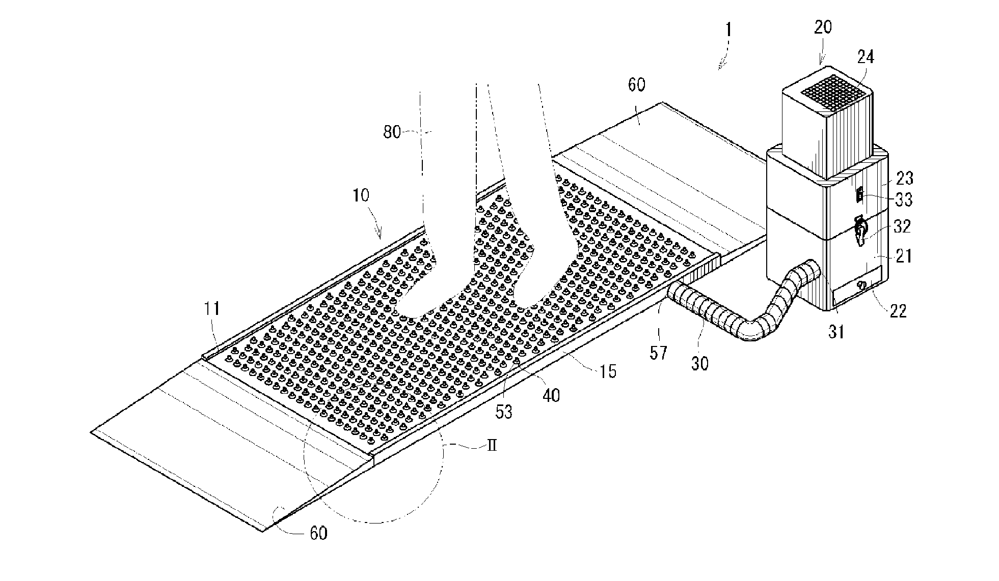
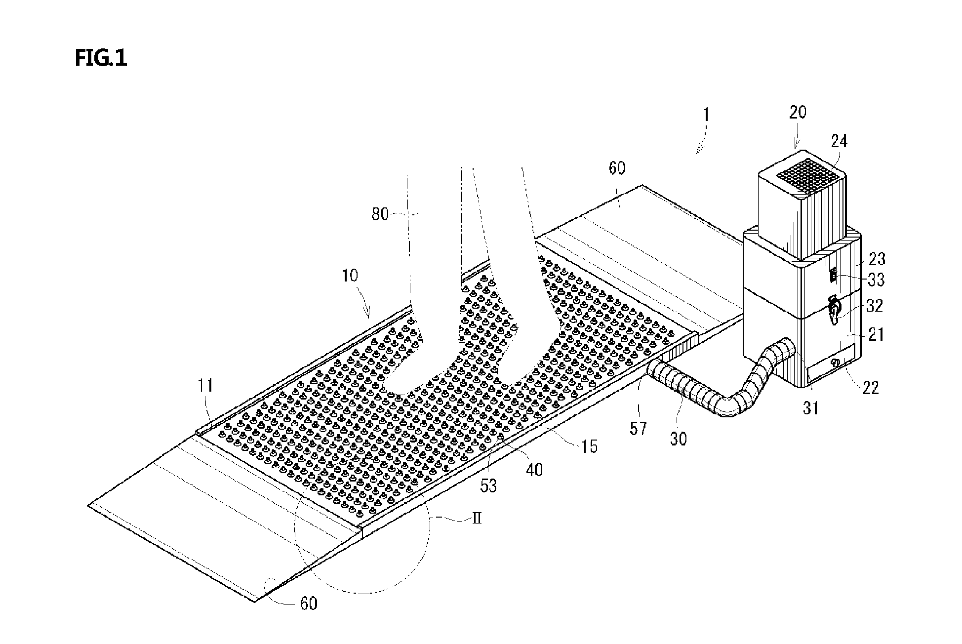
[0040]FIG. 3 is a schematic view illustrating an entire configuration of a dust suction apparatus for shoes according to the present invention

[0041]As illustrated in FIG. 3, the dust suction apparatus for shoes according to the first embodiment of the present invention generally includes: a suction unit 100 which is configured to suck dust separated from shoes by a suction force applied thereto at the time of receiving a load of a visitor; a suction device 200 which is configured to suck the dust separated from the shoes by a motor operated by power supplied thereto; and a vibration device 300 which is configured to horizontally vibrate the suction unit 100 by a vibration motor operated by power supplied thereto.

[0042]The suction unit 100 includes an upper plate on which shoes are placed and elastic actuating members which open suction ports formed in the upper plate when the load of the visitor is applied thereto. Therefore, dust which has fallen into a housing, in which the suctio...

second embodiment

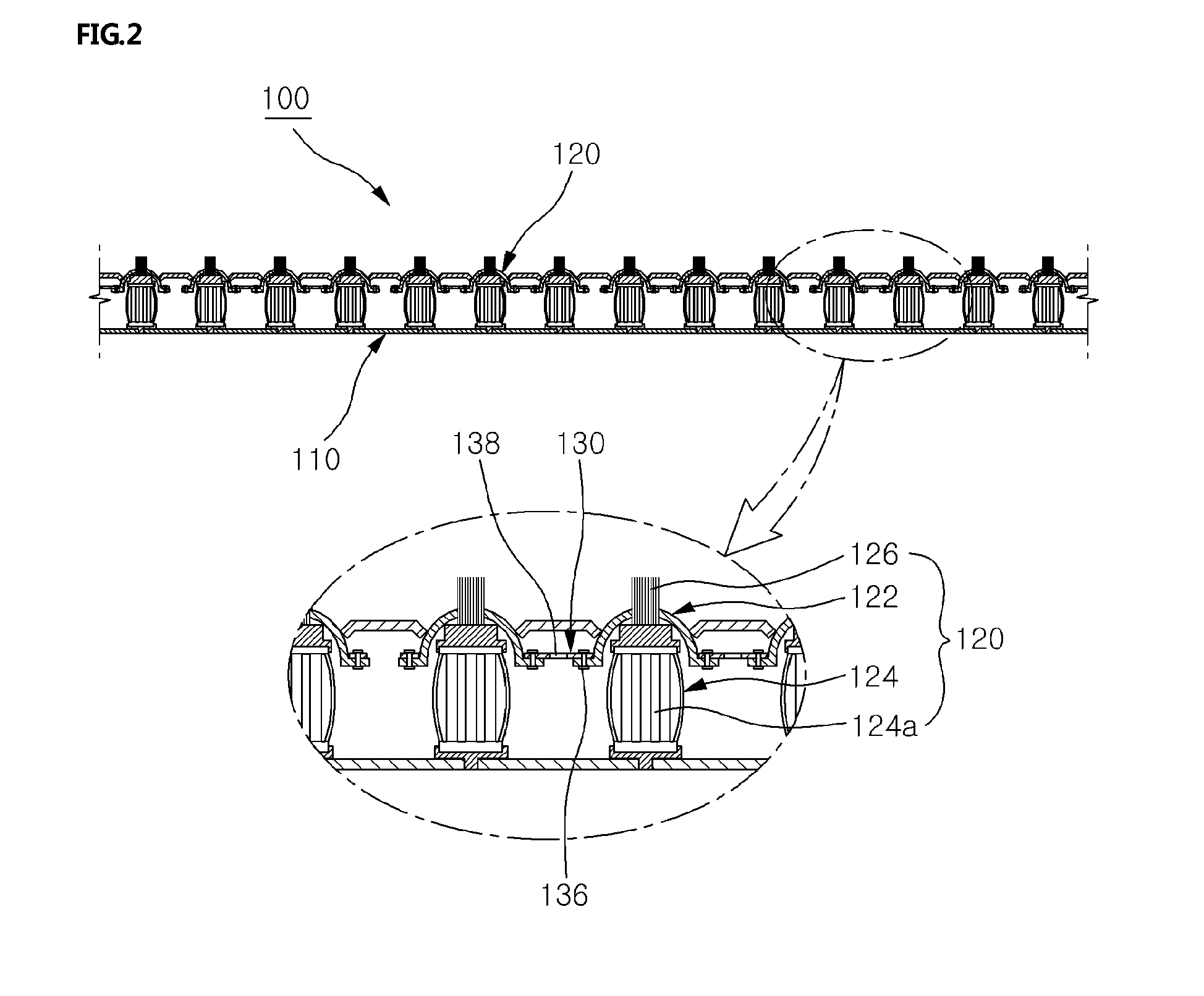
[0076]FIG. 7 is a cross-sectional view illustrating major parts of a dust suction apparatus for shoes according to the present invention.

[0077]As illustrated in FIG. 7, the dust suction apparatus for shoes according to the second embodiment of the present invention generally includes: a suction unit 400 which is configured to suck dust separated from shoes by a suction force applied thereto at the time of receiving a load of a visitor; a suction device which is configured to suck the dust separated from the shoes by a motor operated by power supplied thereto; and a vibration device which is configured to horizontally vibrate the suction unit 400 by a vibration motor operated by power supplied thereto.

[0078]The suction unit 400 includes an upper plate on which the shoes are placed and elastic actuating members which open suction ports formed in the upper plate when the load of the visitor is applied thereto. Therefore, dust which has fallen into a housing, in which the suction unit 4...


PUM


Abstract

Disclosed is a dust suction apparatus includes: an upper plate 110 forming an upper part of a housing, which includes a plurality of suction ports 111 formed therein at a predetermined interval, and is connected with a vibration device 300 so as to be horizontally vibrated; a lower plate 130 forming a lower part of the housing and including a stepped portion formed on an inner side wall along an upper edge portion thereof so as to have the upper plate placed thereon, such that a storage space for storing the dust which has fallen down through the suction ports 111 is defined between the upper plate 110 the lower plate 130; and elastic actuating members 120 disposed between the upper plate 110 and the lower plate 130 to selectively open the suction ports 111 while normally closing the suction ports by elastic force stored therein.

Description

CROSS-REFERENCE TO RELATED APPLICATION[0001]This application claims under 35 U.S.C. §119(a) the benefit of Korean Patent Application No. 10-2013-0053055, filed on May 10, 2013 in the Korean Intellectual Property Office, the entire disclosure of which is incorporated herein by reference.BACKGROUND[0002]1. Technical Field[0003]The present invention relates to a dust suction apparatus for shoes, and more specifically, to a dust suction apparatus for shoes which is installed on an entrance floor of a specific facility to clean dust off shoes and remove dust by sucking up the separated dust.[0004]2. Related Art[0005]Various apparatuses are installed at an entrance of facilities such as factories, laboratories, and hospitals, which should minimize contaminant sources, so as to remove foreign matters such as dust from a body of people moving through the entrance.[0006]In particular, a dust suction apparatus for shoes, which is one of such apparatuses, is used in the removal of foreign matt...

Claims


Application Information

Patent Timeline
Patent Type & Authority Applications(United States)
IPC IPC(8): A47L23/26A47L23/02
CPCA47L23/263A47L23/02A47L23/22
Inventor LEE, JOON-PYO
Owner GM CORP
Why Eureka
Try Eureka