
Device for a security system

a security system and device technology, applied in the field of devices for security systems, can solve the problems of affecting the overall cost of fence preparation, maintenance and replacement, and untidy and unappealing onlookers, and achieve the effects of preventing uneven weight distribution, reducing material costs, and maximising clearan

Inactive Publication Date: 2014-11-13
GALLAGHER ELECTRONICS LTD CO
View PDF0 Cites 1 Cited by
  • Summary
  • Abstract
  • Description
  • Claims
  • Application Information

AI Technical Summary

Benefits of technology

This patent aims to solve the problem of arcing and short circuits between conductive components in high voltage applications, which can lead to fire risks and false alarms. The patent proposes two solutions: physically separating the conductive link from the support post and reducing the visibility of links and hard angles in the design. These solutions also enhance the aesthetic appeal of the design.

Problems solved by technology

However, these systems above have a number of disadvantages as discussed below.
Installation of the conductive links and strainers requires considerable time, skill and effort to provide the desired outcome.
This dramatically affects the overall cost (due to labour) in fence preparation, maintenance and replacement.
Furthermore, as the conductive link and strainer are separate units, the system described above can be untidy and unappealing to the onlooker.
This can be an issue for property holders that require security fences, yet want to maintain an aesthetic appearance to their fence and property.
Wires in fences are prone to loosening over time (due to stretching), and the strainers are often periodically used to re-tension the wires; usually rotation of the ratchet will achieve this result.
However, the conductive links located between the wires can become uneven due to wire adjustment which can add to the untidiness of the fence.
Fixing this unappealing feature requires further time, and ultimately cost.
Furthermore, as the conductive links are typically inflexible, the conductive links only have a certain amount of movement which will ultimately hinder the amount of possible adjustment of the wires.
Again, re-adjustment of the conductive links to address this problem can take further time and effort.
Such systems can also present a risk that a perpetrator can cut the security wire upstream of the conductive link's position to avoid triggering an alarm.

Method used


Image

  • Device for a security system
  • Device for a security system
  • Device for a security system

Examples


Embodiment Construction

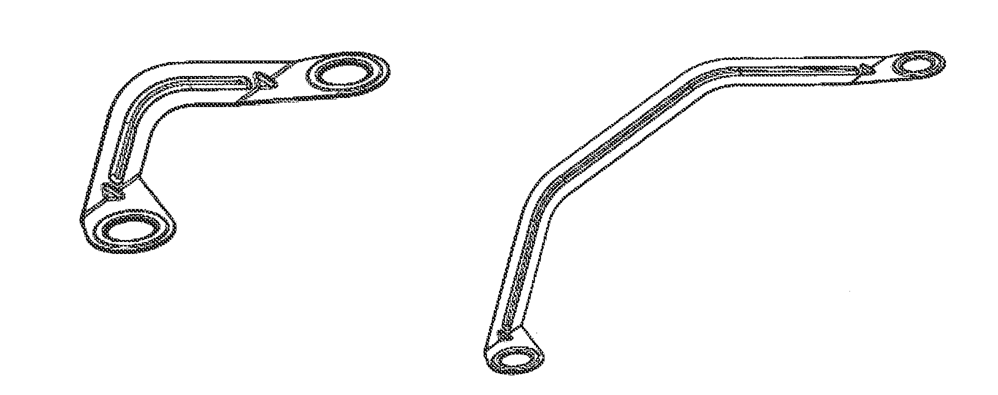
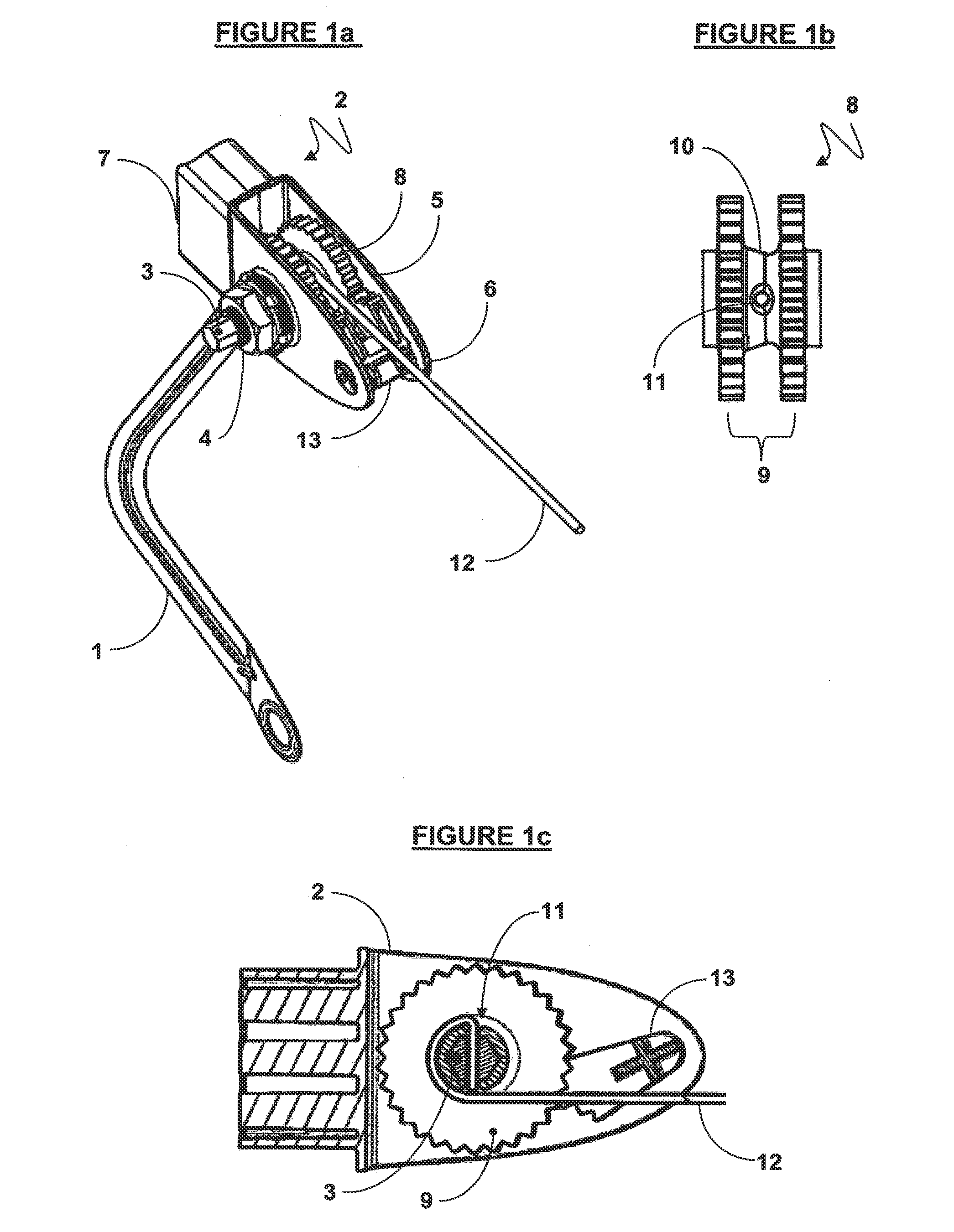
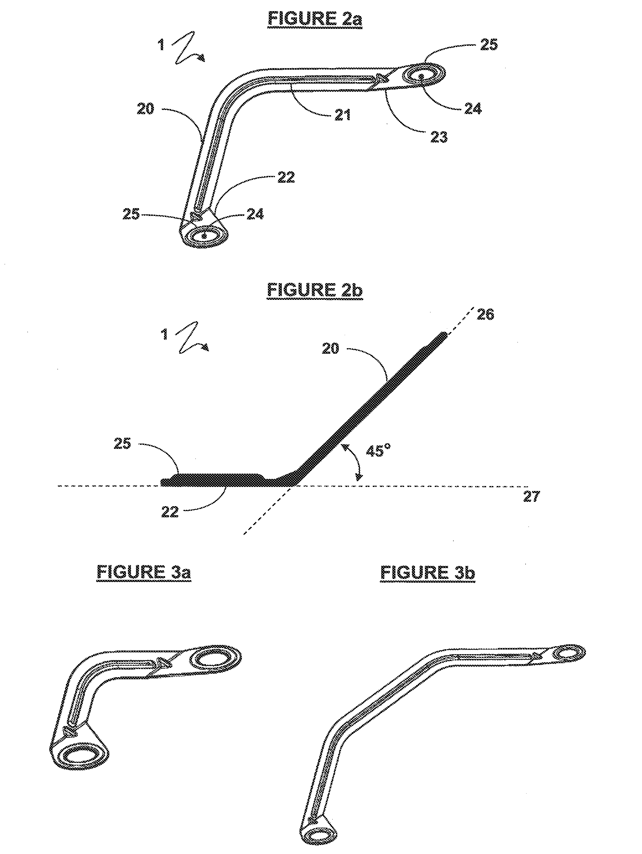
[0066]As shown generally in FIG. 1a, a conductive link (1) of the present invention is illustrated in conjunction with a strainer (2).

[0067]The strainer (2) is made substantially of a plastics material except for a conductive component (3), and a fastener in the form of a nut (4). The strainer (2) includes a housing with a head portion with rounded sides (5), rounded tips (6) and a box shaped backing portion (7).

[0068]The strainer (2) includes a tensioning device in the form of a ratchet (8). The ratchet (8) may be made of either a non-conductive material such as plastic, or a conductive material.

[0069]FIG. 1b shows that the ratchet (8) has two “wheels” (9) joined by a central portion (10). The ratchet (8) has an aperture (11) which passes through the central portion (10) of the ratchet (8).

[0070]As illustrated by FIG. 1c, a wire (12) is passed through the aperture (11), where it contacts the conductive component (3), which in turn projects from the housing as illustrated in FIG. 1a...


PUM

PropertyMeasurementUnit
Angleaaaaaaaaaa
Angleaaaaaaaaaa
Shapeaaaaaaaaaa

Abstract

A conductive link and method of use are provided in conjunction with constructing a security system. The link includes a substantially flat elongate body aligned substantially within a first plane. At least one tab extends from each end of the body, each tab having an attachment portion configured to connect an end of the conductive link directly or indirectly to an electric fence strainer. The tabs and attachment portions are positioned substantially within a second plane oriented to be substantially nonparallel to the first plane.

Description

TECHNICAL FIELD[0001]The present invention relates to a device for a security system and its method of use. In particular, the present invention relates to a conductive link for use in providing a conductive path between electric fence strainers.STATEMENT OF CORRESPONDING APPLICATIONS[0002]This application is based on the specification filed in relation to New Zealand Patent Application Number 596786 dated 30 Nov. 2011 the entire contents of which are incorporated herein by reference.BACKGROUND ART[0003]This invention will be discussed in relation to improvements in accessories used with wire in an electric security fence. However, a skilled person will appreciate that the principles of the present invention can be applied to tensioning lengths of other materials in different situations and is not necessarily limited to security electric fences and / or wire.[0004]Strainers have been in use for numerous years to aid the tensioning of wire in electrified fences, such as those used in t...

Claims


Application Information

Patent Timeline
IPC IPC(8): E04H17/26A01K3/00E04H17/04E04H17/06H05K13/00H02G3/02
CPCE04H17/266H05K13/0023H02G3/02E04H17/04E04H17/06A01K3/005Y10T29/49117E04H17/127H05K13/00
Inventor MALINS, CRAIG DAVIDTYRRELL, KAREN RUTH
Owner GALLAGHER ELECTRONICS LTD CO
Learn More