Touch panel and touch display

Active Publication Date: 2014-11-13
HANNSTAR DISPLAY CORPORATION
View PDF11 Cites 7 Cited by
  • Summary
  • Abstract
  • Description
  • Claims
  • Application Information

AI Technical Summary

Benefits of technology

[0009]The invention is directed to a touch panel and a touch display with a novel structure to reduce the defects existing in the conventional touch panel. Specifically, a comp

Problems solved by technology

Thereby, the resultant visibility of the touch panel 10 is not satisfactory and causes inconvenience to users.
In view of the abo

Method used


Image

  • Touch panel and touch display
  • Touch panel and touch display
  • Touch panel and touch display

Examples


Example

[0032]The accompanying drawings are included to provide a further understanding of the invention, and are incorporated in and constitute a part of this specification. The drawings illustrate embodiments of the invention and, together with the description, serve to explain the principles of the invention.

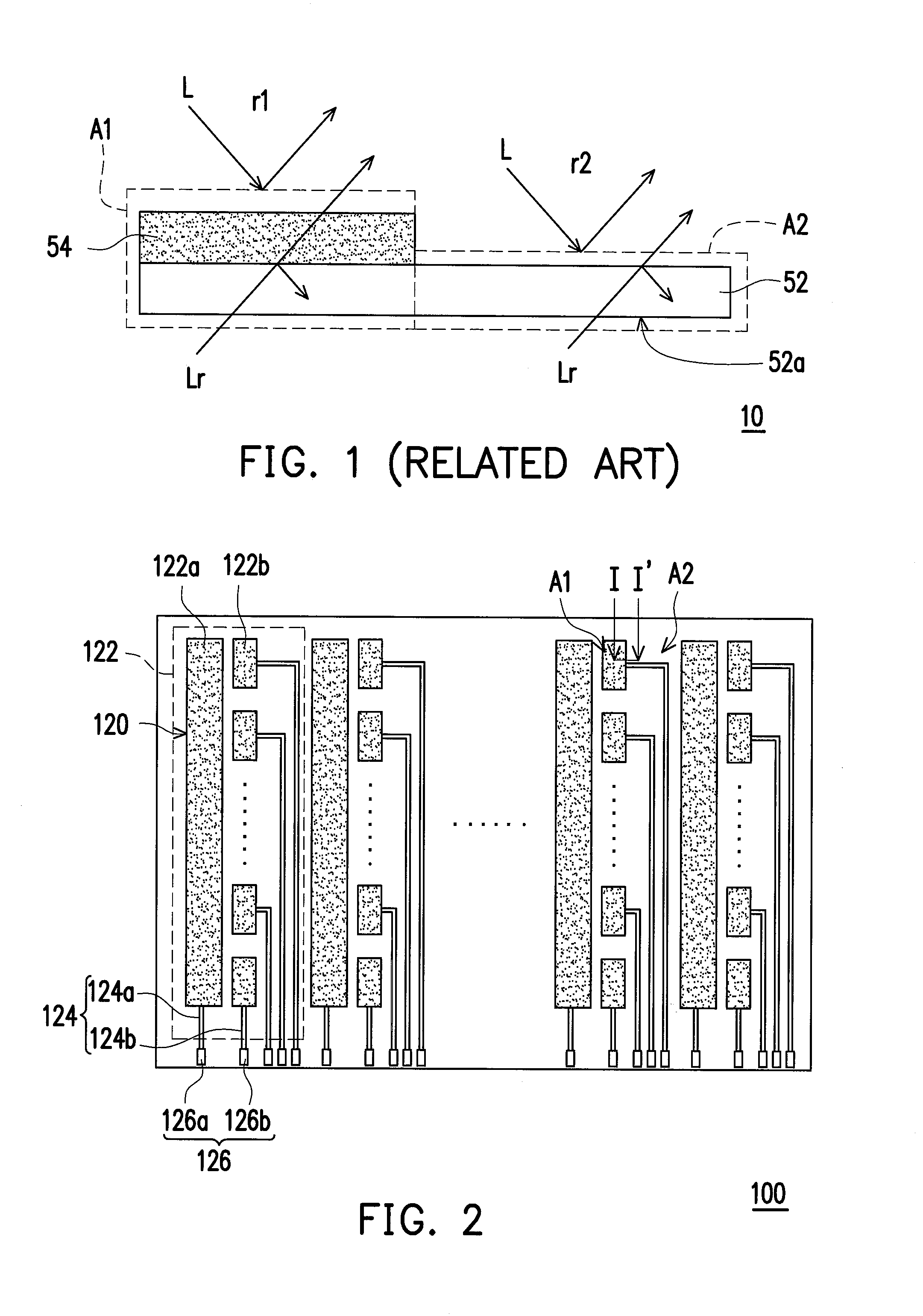
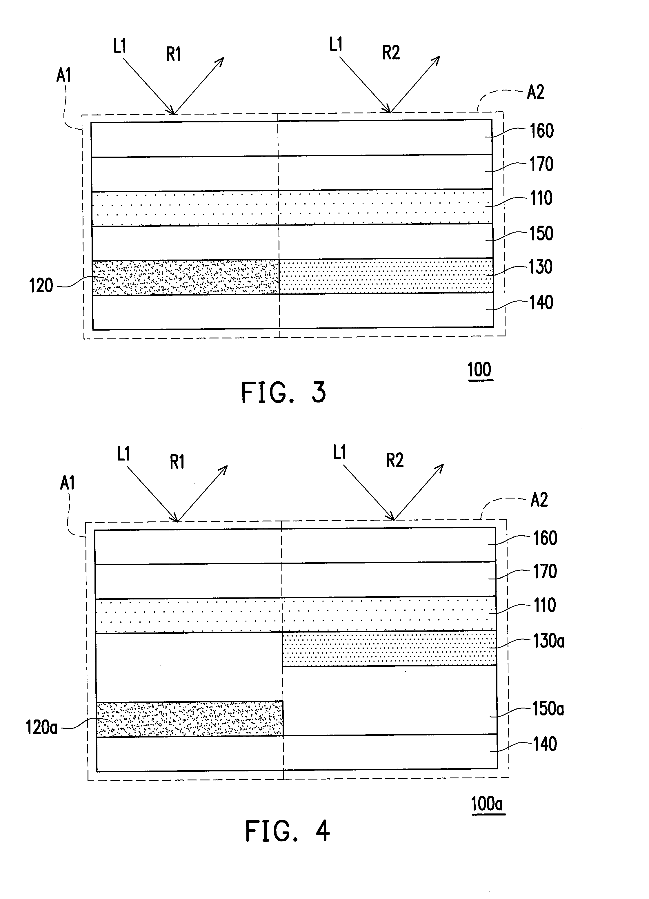
[0033]FIG. 2 is a schematic partial top view of a touch panel according to an embodiment of the invention. FIG. 3 is a schematic partial cross-sectional view taken along a line I-I′ in FIG. 2. With reference to FIG. 2 and FIG. 3, the touch panel 100 described in the present embodiment includes a first substrate 110, a touch sensing layer 120, a compensation pattern layer 130, a second substrate 140, and a first optical adhesive layer 150. The touch sensing layer 120 includes a plurality of electrode sets 122 arranged in parallel, and each of the electrode sets 122 includes a scan electrode 122a and a plurality of sensing electrodes 122b. The touch sensing layer 120 described herein i...


PUM


Abstract

A touch panel that includes a first substrate, a touch sensing layer, a compensation pattern layer, a second substrate, and a first optical adhesive layer is provided. The touch sensing layer includes a plurality of electrode sets arranged in parallel, and each of the electrode sets includes a scan electrode and a plurality of sensing electrodes. An orthogonal projection of the touch sensing layer on the first substrate is not overlapped with an orthogonal projection of the compensation pattern layer on the first substrate. The compensation pattern layer and the touch sensing layer are located between the first substrate and the second substrate. The first optical adhesive layer is located between the first substrate and the second substrate. A touch display is also provided.

Description

CROSS-REFERENCE TO RELATED APPLICATION[0001]This application claims the priority benefit of China application serial no. 201310169592.5, filed on May 9, 2013. The entirety of the above-mentioned patent application is hereby incorporated by reference herein and made a part of this specification.BACKGROUND OF THE INVENTION[0002]1. Field of the Invention[0003]The invention relates to a touch panel and a touch display; more particularly, the invention relates to a touch panel and a touch display which are characterized by great visibility.[0004]2. Description of Related Art[0005]As information technology, wireless mobile communication, and information appliances have been rapidly developed and applied in recent years, various information products have utilized touch panels as input devices in replacement of conventional input devices (e.g., keyboards or mice), so as to ensure the convenience, the compactness, and the user-friendly design of the information products.[0006]FIG. 1 is a sch...

Claims


Application Information

Patent Timeline
IPC IPC(8): G06F1/16
CPCG06F3/044G02F2201/38G06F1/1692G06F3/0443
Inventor YU, CHIA-HUALIN, YU-CHENGSU, PING-YUANTSAI, KUN-HUALEE, HSING-YING
Owner HANNSTAR DISPLAY CORPORATION
Why Eureka
Try Eureka