Temporary work light string with variably-positionable and re-positionable readily-replaced lamp, optionally with integral hangers, that are optionally electrically connected to plural electrical circuits

Active Publication Date: 2014-11-20
MAHR CASEY JAMES
View PDF4 Cites 11 Cited by
  • Summary
  • Abstract
  • Description
  • Claims
  • Application Information

AI Technical Summary

Benefits of technology

The work light string described in this patent allows for easy disassembly and reuse of the discussed parts. The assemblies can be plugged anywhere along the length of the cord / cable and can be detached from the cord / cable without causing damage. The insulation of the cord / cable is self-healing and closes the penetration holes, making the cord / cable and assemblies with their contained electric lamps suitable for re-use. Additionally, failure of one electrical circuit does not cause failure of the electric lights of the work light string that are electrically connected to the other circuit, providing redundancy in lighting.

Problems solved by technology

However, the CSA designation for this type of cord (STW) carries no recognition for oil resistance.
“Although manufactured like a thermoset product and able to perform in temperatures up to 105 degrees Celsius / 221 degrees Fahrenheit, TPE may not stand up in environments where extreme heat and hot oil are factors.
When exposed to such circumstances, the cord may disfigure or melt, making it useless.’
Such a construction is, almost by definition, likely unsuitable in detail for the illumination of the interior spaces, or rooms, of a building which rooms are typically not linear, and which are accessed through doors and windows at which points lamps may be inappropriate for, among other reasons, shining in the eyes of persons passing or looking through such portals.
More troublesome than sub-optimal lamp locations are the quite frequent occurrences during construction when more light is needed at a specific location.
The operation of moving an entire light string so as to move and relocate but a single lamp may become labor intensive and may even require the labor of more than one person.
Further, and more seriously, lamps that are located in fixed positions along the length of a temporary power cord most typically cannot be replaced if damaged.
The only alternative to discarding the entire work light cord is to cut out a damaged light and splice the cord back together in an improved manner, typically leaving both an undesirable bulge on the cord and dimensional unevenness in the location of lights along the cord.
This repair requires materials and time, and is seldom done even by skilled electricians upon their own work light cords.
Moreover, the ability to power additional loads from these work light cords—such as at a receptacle at the end of the cord o by screwing into an Edison socket normally taking an light bulb—is limited.

Method used


Image

  • Temporary work light string with variably-positionable and re-positionable readily-replaced lamp, optionally with integral hangers, that are optionally electrically connected to plural electrical circuits
  • Temporary work light string with variably-positionable and re-positionable readily-replaced lamp, optionally with integral hangers, that are optionally electrically connected to plural electrical circuits
  • Temporary work light string with variably-positionable and re-positionable readily-replaced lamp, optionally with integral hangers, that are optionally electrically connected to plural electrical circuits

Examples


Embodiment Construction

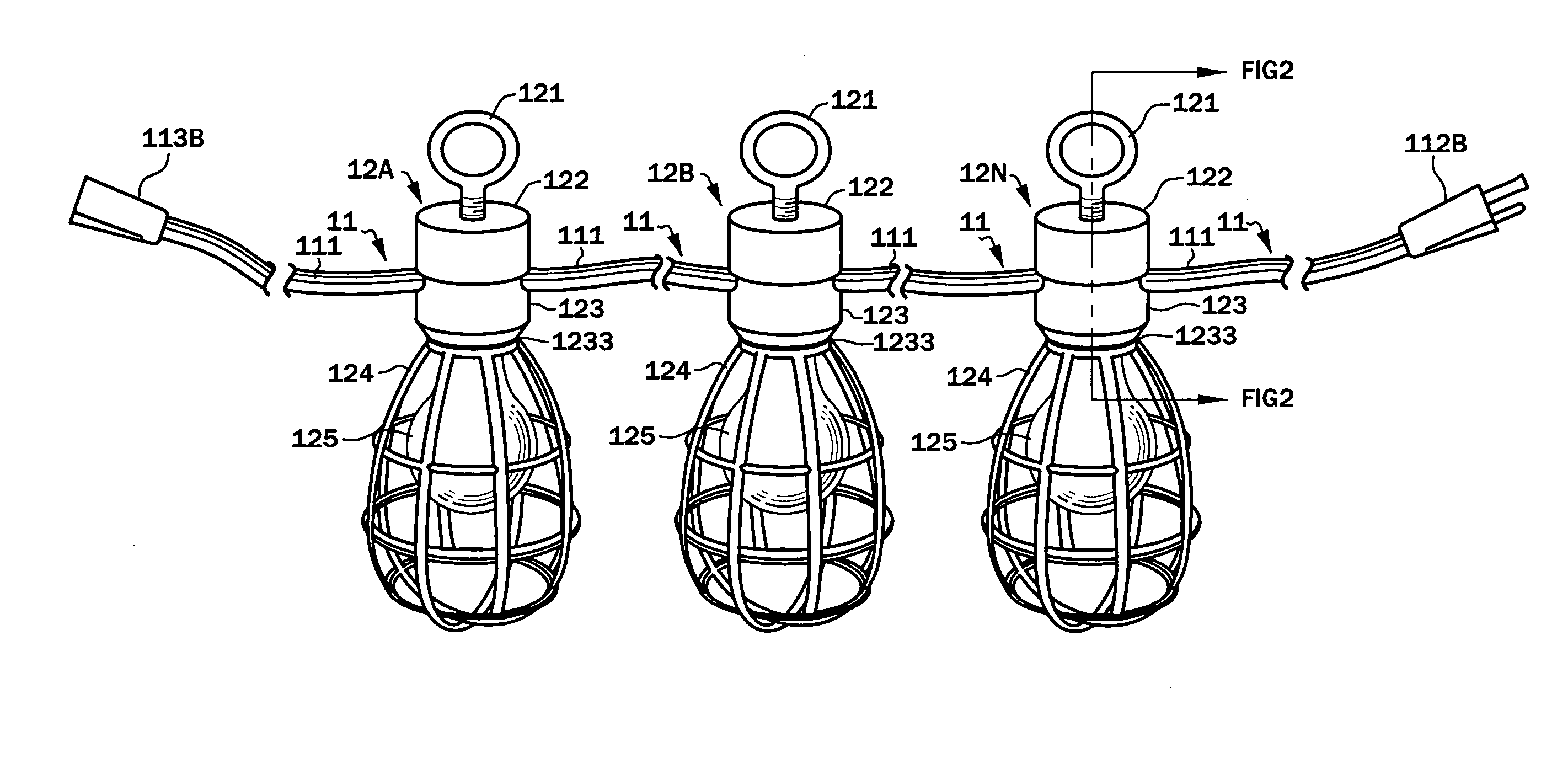
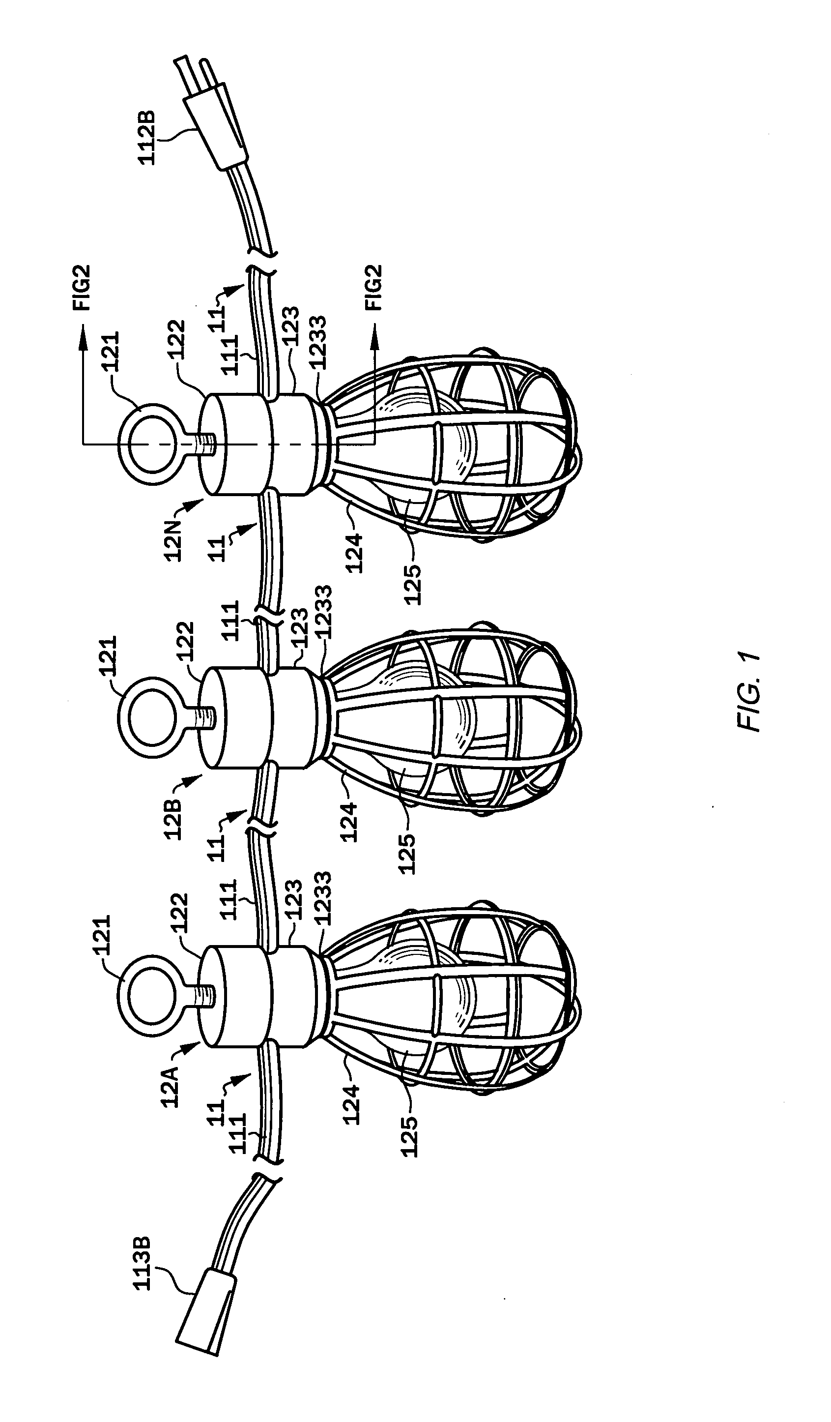
[0048]A preferred embodiment of a work light string 1 with variably positionable, re-positionable and replaceable lamps 12 in accordance with the present invention is shown in diagrammatic view in FIG. 1.

[0049]The work light string 1 consists of a cable 11 proceeding from a first-end standard three-prong male electrical connector, or plug, 112B as to attach along its length a number of lamps—of which exemplary lamps 12A, 12B, . . . 12N are shown—to finally optionally terminate in a standard three prong female electrical connector, or plug, 113B. The cable 11 can electrically connect to, and communicate power ever but a single electrical circuit, but can alternatively connect to, and communicate electrical power over, two separate electrical circuits, as will be illustrated in conjunction with FIG. 3c. Namely, some of the lamps 12 can be oriented relative to the cable 11 so as to connect to a first electrical circuit therein, while other of the lamps 12 are reversed 180 degrees (rela...


PUM


Abstract

A work light string removably physically mounts and electrically attaches lamps anywhere along it is length, with ready hand positioning and re-positioning of desired numbers of lamps at desired positions, and replacement of damaged lamps. The work light string can have one, or, more preferably two separate electrical circuit in which case each lamp and any external electrical load(s) can be powered by either circuit.

Description

BACKGROUND OF THE INVENTION[0001]1. Field of the Invention[0002]The present invention generally concerns a portable cord, also known as portable cordage, for temporary deployment that attaches, permissibly among other things, temporary work lamps, or lights, along its length, thus nominally a “temporary work light string”.[0003]The present invention particularly concerns (1) the positioning of lamps, or lights, along the length of a temporary work light string, and (2) the management of electrical circuits within a temporary work light string and within any devices, including lamps or lights, that are electrically connected to such temporary work light string.[0004]2. Background of the Invention[0005]2.1 Portable Cords[0006]The present invention will be seen to involve a portable temporary power cord, or cable, that can physically attach and electrically connect along its length, among other things, work lamps.[0007]According to the entry “Portable Cord” appearing circa 2012 in Wiki...

Claims


Application Information

Patent Timeline
IPC IPC(8): F21S4/00
CPCF21S4/001F21S4/10F21V15/02F21V23/001F21W2131/1005
Inventor MAHR, CASEY JAMES
Owner MAHR CASEY JAMES
Why Eureka
Try Eureka