

Plug for use in piercing mill
a plug and mill technology, applied in the field of plugs, can solve the problems of shortening the useful life of the plug, reducing the length of the plug, and reducing the number of re-grinding, so as to reduce the re-grinding allowance, prevent erosion, and increase the diameter of the hole in the billet.
- Summary
- Abstract
- Description
- Claims
- Application Information
AI Technical Summary
Benefits of technology
Problems solved by technology
Method used
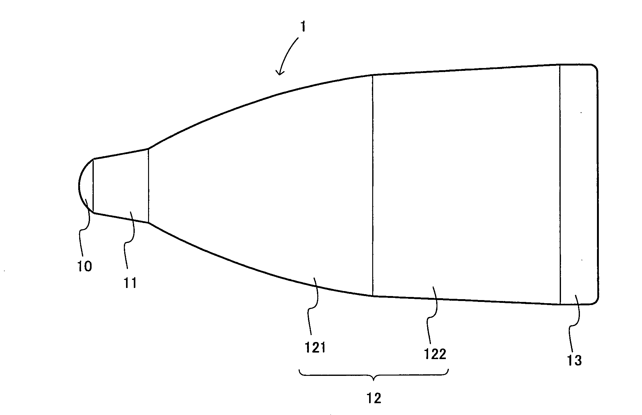
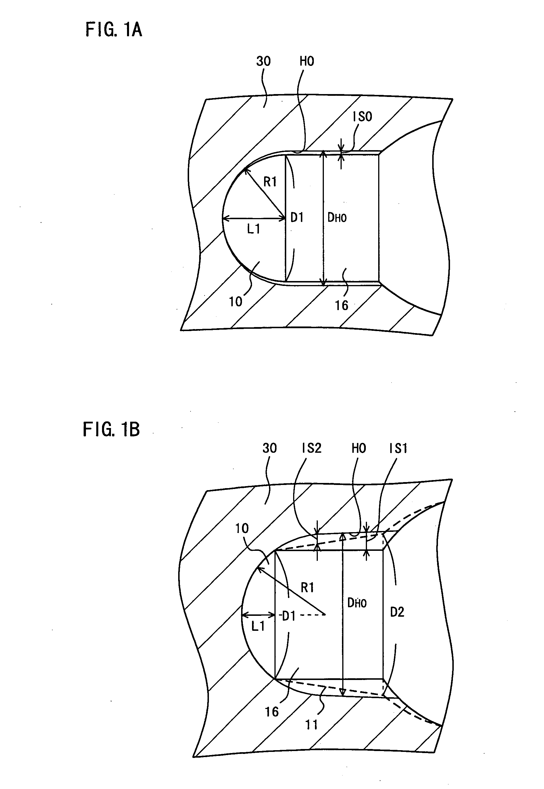
Image

Examples
first example
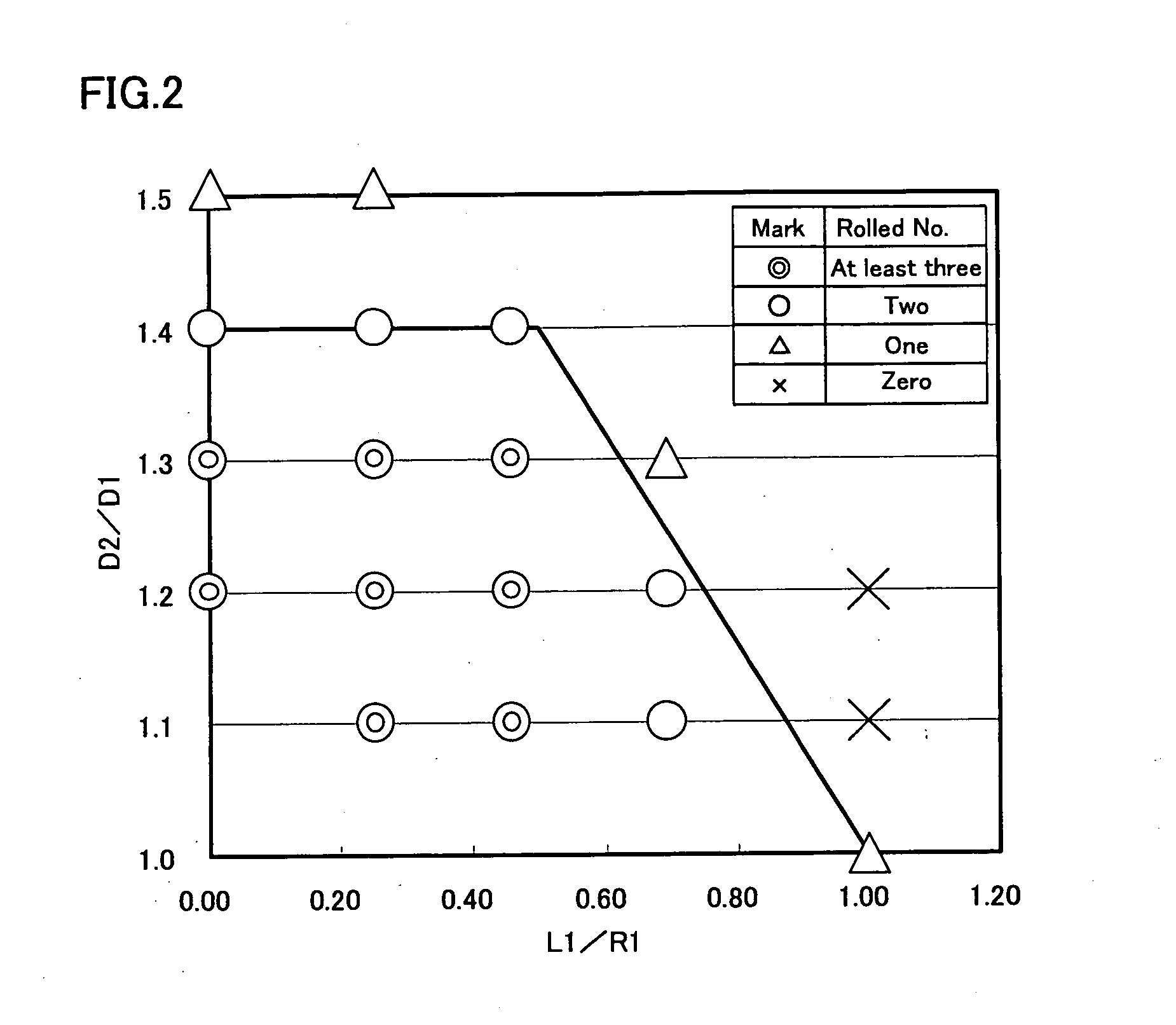
[0064]Using plugs having shapes in FIGS. 9 and 10 and Table 1, billets were pierced and rolled, and the plugs were examined for their useful lives.
TABLE 1item3457891011121.8 − 0.8 × L1 / 0.52.56αD3L1L2L3No.L1 / R1D2 / D1R1D1D1L1 + L2degreemmmmmmmmComp.11.001.01.008.040.015.00.060.08.007.0060.0ExampleComp.21.001.11.008.040.015.06.560.08.007.0060.0ExampleComp.31.001.21.008.040.015.012.960.08.007.0060.0ExampleInv.40.701.11.248.040.015.05.060.05.849.1660.0ExampleInv.50.701.21.248.040.015.09.960.05.849.1660.0ExampleComp.60.701.31.248.040.015.014.760.05.849.1660.0ExampleInv.70.461.1—8.040.015.04.360.04.3810.6260.0ExampleInv.80.461.2—8.040.015.08.660.04.3810.6260.0ExampleInv.90.461.3—8.040.015.012.760.04.3810.6260.0ExampleInv.100.461.4—8.040.015.016.860.04.3810.6260.0ExampleInv.110.251.1—8.040.015.03.860.03.0611.9460.0ExampleInv.120.251.2—8.040.015.07.660.03.0611.9460.0ExampleInv.130.251.3—8.040.015.011.460.03.0611.9460.0ExampleInv.140.251.4—8.040.015.015.060.03.0611.9460.0ExampleComp.150.251.5—...
example 2
[0074]The plugs designated as test numbers 20 to 22 did not have a corner radius Rc, but the other shape and size were the same as those of the plugs designated as test numbers 7 to 9. More specifically, the plug designated as test number 20 had the same size as that of the plug designated as test number 7 except for the corner radius Rc. Similarly, the plugs designated as test numbers 21 and 22 had the same sizes as those of the plugs designated as test numbers 8 and 9, respectively, both except for the corner radius Rc.
[0075]As a result of examination in Example 1, with the plugs designated as test numbers 20 to 22, the roll number was three or more similarly to the plugs designated as test numbers 7 to 9. Therefore, in order to examine the effect of the corner radius, the plugs designated as test numbers 7 to 9 and 20 to 22 were further examined for their rolled numbers.
[0076]As a result of examination, the plugs designated as test numbers 20 to 22 having no corner radius Rc both...
example 3
[0077]The relation between the spherical surface shapes of the tip end portions and the occurrence of erosion was examined. More specifically, the plugs designated as test numbers 7 and 11, 8 and 12, and 9 and 13 having almost the same taper half angles α for their taper portions and different values for L1 / R1 were examined for the rolled numbers. As a result, for each of the plugs, the rolled number was four. Therefore, the plugs were re-grinded in the axial direction until the eroded portions were removed, and the plugs were examined for their re-grinding allowances. More specifically, the plugs were each re-grinded by 0.5 mm in the axial direction and it was determined by visual inspection whether there was still an eroded portion remaining after the re-grinding. When the eroded portion remained, the plug was re-grinded for another 0.5 mm. The result of examination is given in Table 3.
TABLE 3re-cuttingTest No.L1 / R1allowance (mm)70.4611.0110.259.580.4610.0120.258.090.467.5130.257....
PUM
| Property | Measurement | Unit |
|---|---|---|
| Volume | aaaaa | aaaaa |
| Length | aaaaa | aaaaa |
| Diameter | aaaaa | aaaaa |
Abstract
Description
Claims
Application Information