
Film forming apparatus and film forming method

a metal film and film forming technology, applied in the direction of electrolysis process, semiconductor devices, electrolysis components, etc., can solve the problems of uneven thickness of metal film, impeded current flow from the location where oxygen gas has accumulated (i.e., a part of the surface of the anode) toward the cathode, etc., and achieve the effect of few defects

Active Publication Date: 2017-09-05
TOYOTA JIDOSHA KK
View PDF17 Cites 1 Cited by
  • Summary
  • Abstract
  • Description
  • Claims
  • Application Information

AI Technical Summary

Benefits of technology

[0011]The invention thus provides a film forming apparatus and a film forming method capable of stably forming a metal film of uniform thickness having few defects.
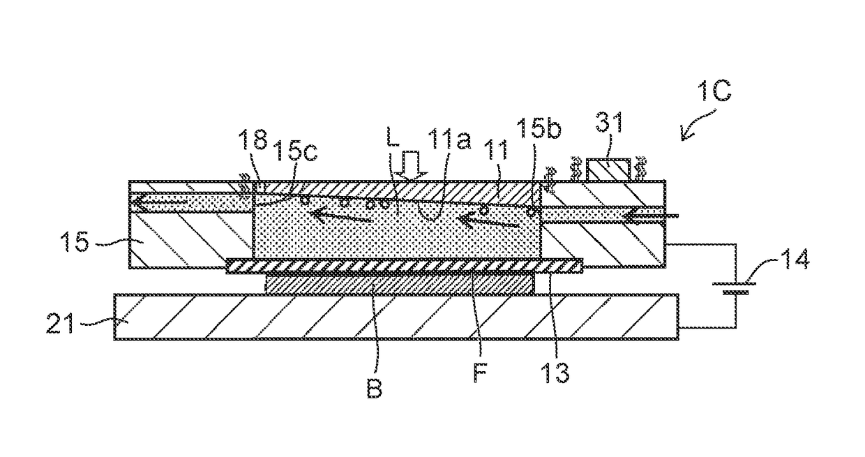
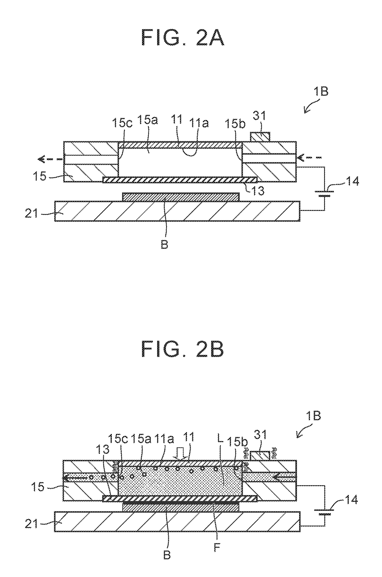
[0019]Oxygen gas produced at the anode has a lighter specific gravity than the electrolytic solution, so it tends to move upward more easily through the electrolytic solution. According to the above aspect, a flow of electrolytic solution that is inclined upward from the liquid supply port toward the liquid discharge port is able to be formed by forming the liquid discharge port in a position higher than the liquid supply port. Therefore, oxygen gas produced at the anode is easily discharged with the electrolytic solution from the liquid discharge portion.
[0021]According to this aspect, the oxygen gas produced at the surface of the oscillating anode easily moves upward along the inclined surface of the anode, from the liquid supply port toward the liquid discharge port. As a result, the oxygen gas produced at the anode is easily discharged, together with the electrolytic solution, from the liquid discharge port.
[0023]According to this aspect, the gas discharge port is formed in a position higher than the liquid discharge port. Therefore, the oxygen gas produced at the anode is able to be discharged from the gas discharge port before being discharged from the liquid discharge port. Consequently, the amount of oxygen gas included in the electrolytic solution that is discharged from the liquid discharge port is able to be reduced. As a result, the electrolytic solution is able to be suitably reused, e.g., the electrolytic solution is able to be circulated to the apparatus.
[0035]According to this aspect, the oxygen gas produced at the surface of the oscillating anode easily moves upward along the inclined surface of the anode. As a result, the oxygen gas produced at the anode is easily discharged, together with the electrolytic solution, from between the anode and the solid electrolyte membrane.

Problems solved by technology

Therefore, even if voltage is applied between the anode and the substrate that is the cathode, the flow of current from the location where the oxygen gas has accumulated (i.e., a part of the surface of the anode) toward the cathode may be impeded.
As a result, a defect such as a pinhole may be produced in the formed metal film, or the thickness of the metal film may be uneven.

Method used


Image

  • Film forming apparatus and film forming method
  • Film forming apparatus and film forming method
  • Film forming apparatus and film forming method

Examples


Embodiment Construction

[0055]Hereinafter, a film forming apparatus capable of suitably carrying out a metal-film forming method according to example embodiments of the invention will be described.

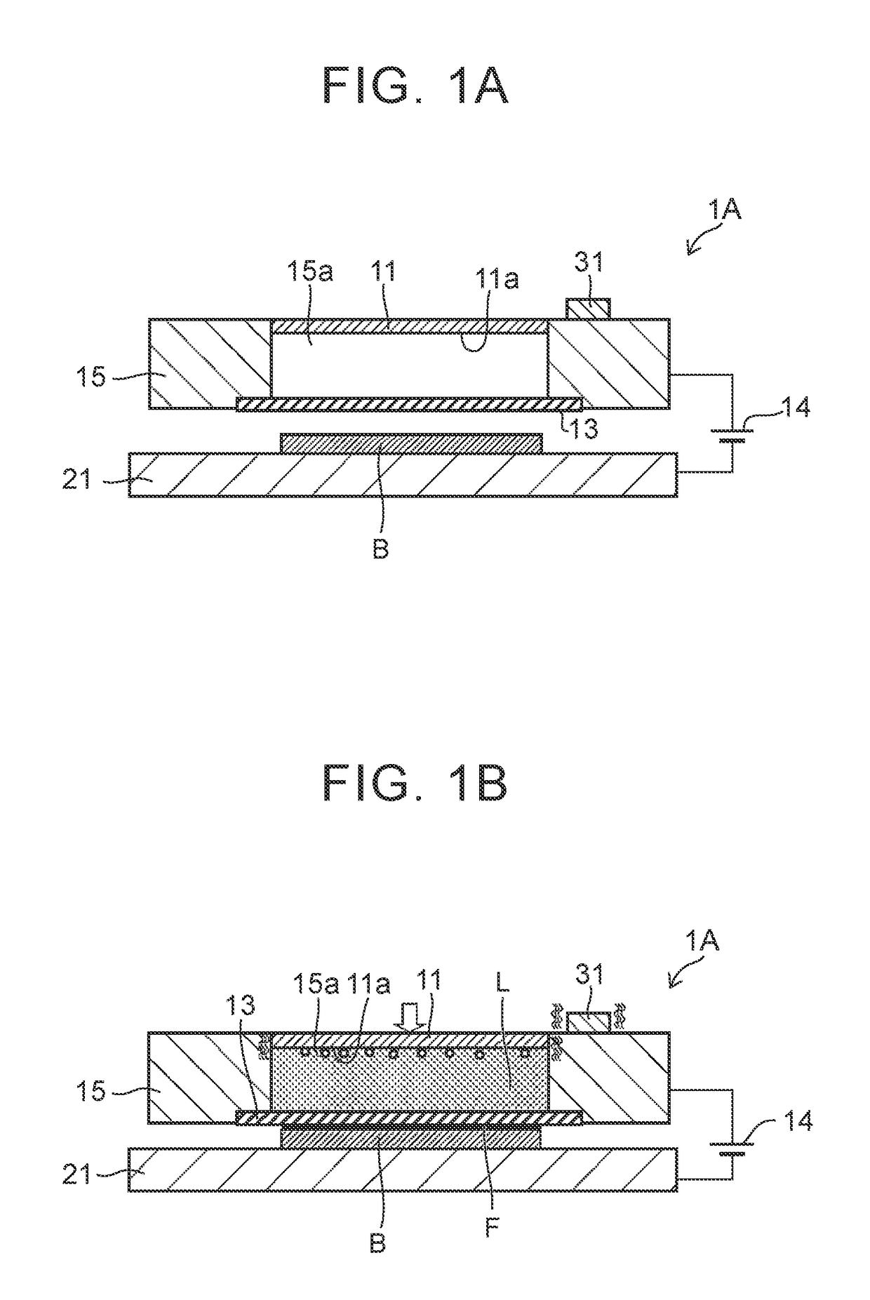
[0056]FIGS. 1A and 1B are conceptual diagrams showing frame formats of a film forming apparatus 1A for forming a metal film F according to a first example embodiment of the invention. FIG. 1A is a sectional view showing a frame format of a state of the film forming apparatus 1A before forming a film, and FIG. 1B is a sectional view showing a frame format of a state of the film forming apparatus 1A when a film is being formed.

[0057]As shown in FIGS. 1A and 1B, the film forming apparatus 1A is an apparatus that deposits metal from metal ions, and forms a metal film from the deposited metal on a surface of a substrate B. Here, a substrate made of metal material such as aluminum, or a substrate formed by forming a metal base layer on a treated surface of a resin or silicon substrate, may be used as the substrate B.

[0...


PUM

PropertyMeasurementUnit
frequencyaaaaaaaaaa
thickaaaaaaaaaa
thicknessaaaaaaaaaa

Abstract

A film forming apparatus includes: an anode; a solid electrolyte membrane that is arranged between the anode and an substrate that serves as a cathode, and that contains metal ions; a power supply that applies a voltage between the anode and the substrate in a state in which the solid electrolyte membrane is in contact with the substrate from above; and an oscillating portion configured to oscillate at least the anode in the state in which the solid electrolyte membrane is in contact with the substrate.

Description

INCORPORATION BY REFERENCE[0001]The disclosure of Japanese Patent Application No. 2015-048021 filed on Mar. 11, 2015 including the specification, drawings and abstract is incorporated herein by reference in its entirety.BACKGROUND OF THE INVENTION[0002]1. Field of the Invention[0003]The invention relates to a metal-film forming apparatus and a metal-film forming method capable of suitably forming a metal film by applying voltage between an anode and substrate, and depositing metal from metal ions contained in a solid electrolyte membrane onto a surface of the substrate.[0004]2. Description of Related Art[0005]Conventionally, when manufacturing an electronic circuit substrate or the like, a nickel film is formed on a surface of a substrate in order to form a nickel circuit pattern. As film forming technology of such a metal film, technology that forms a metal film by a plating process such as a non-electrolytic plating process, or that forms a metal film by a PVD method such as sputt...

Claims


Application Information

Patent Timeline
Patent Type & Authority Patents(United States)
IPC IPC(8): C25D17/12C25D17/00C25D5/08C25D3/00C25D5/04C25D7/12
CPCC25D17/002C25D3/00C25D5/04C25D5/08C25D17/12C25D7/123C25D5/00C25D21/04
Inventor HIRAOKA, MOTOKIYANAGIMOTO, HIROSHISATO, YUKI
Owner TOYOTA JIDOSHA KK
Learn More