Method of forming a silicon nitride layer

a technology of silicon nitride and thin film, which is applied in the direction of resistive material coating, superimposed coating process, liquid/solution decomposition chemical coating, etc., can solve the problem that the silicon nitride layer within the micro electro-mechanical system is more susceptible to peeling than the silicon nitride layer of a conventional device, and the ammonia with a relatively small gas flow rate cannot diffuse to the top of the deposition furnace. problems, to achieve th

Active Publication Date: 2007-06-12
MACRONIX INT CO LTD
View PDF6 Cites 144 Cited by
  • Summary
  • Abstract
  • Description
  • Claims
  • Application Information

AI Technical Summary

Benefits of technology

[0010]In the aforementioned process, the uniform gas injection apparatus distributes nitrogen, which has a smaller flow rate, uniformly inside the deposition furnace. Therefore, the silicon-containing gases and the nitrogen-contain gases can mix together in an substantially similar proportion everywhere inside the deposition furnace so that a silicon nitride layer with an uniform thickness and a low internal stress is formed on each wafer within the wafer boat. In other words, wafers with a thicker silicon nitride layer and a lower internal stress that meet the demands for fabricating micro electro-mechanical systems are produced.

Problems solved by technology

However, in the process of deposition, ammonia with a relatively small gas flow rate can not diffuse to the top of the deposition furnace.
Therefore, the silicon nitride layer on various wafers within the same wafer boat will show low uniformity.
Hence, the silicon nitride layer within a micro electro-mechanical system is more vulnerable to peeling than the silicon nitride layer of a conventional device if internal stress is high.
Consequently, the inkjet print head will fail to work.
Hence, if a conventional vertical deposition furnace is used to fabricate the silicon nitride layer on wafers for forming the micro electro-mechanical system, the mass production of the deposition furnace will be very hard.

Method used


Image

  • Method of forming a silicon nitride layer
  • Method of forming a silicon nitride layer

Examples


Embodiment Construction

[0016]Reference will now be made in detail to the present preferred embodiments of the invention, examples of which are illustrated in the accompanying drawings. Wherever possible, the same reference numbers are used in the drawings and the description to refer to the same or like parts.

[0017]In the following, a vertical deposition furnace is used to illustrate the method of the present invention.

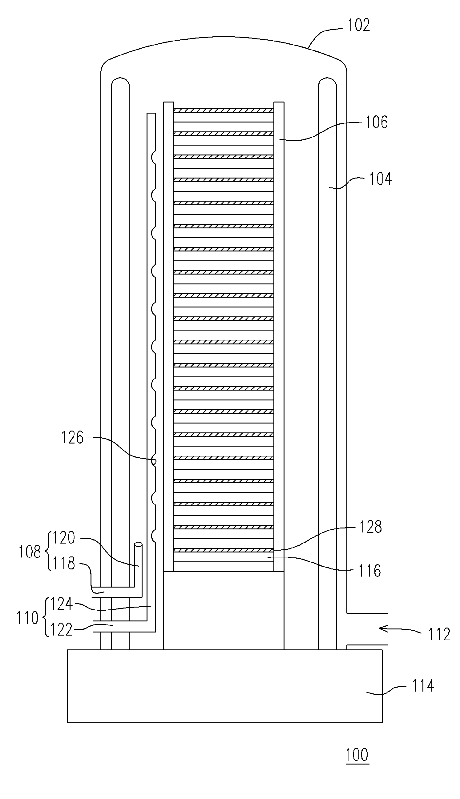
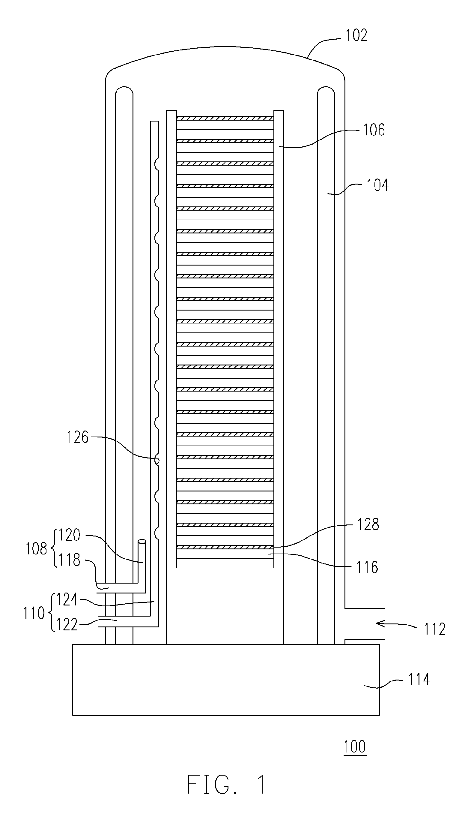
[0018]FIG. 1 is a schematic cross-sectional view of a vertical deposition furnace according to one preferred embodiment of the present invention. Before performing the process of depositing silicon nitride over a set of wafers, a vertical deposition furnace 100 as shown in FIG. 1 is provided. The vertical deposition furnace 100 comprises an outer tube 102, an inner tube 104, a wafer boat 106, an air injector 108 and a uniform gas injection apparatus 110. The uniform gas injection apparatus 110 can be a multi-aperture gas injector or other gas injection apparatus suitable for evenly distribu...


PUM

PropertyMeasurementUnit
pressureaaaaaaaaaa
gas flow rateaaaaaaaaaa
mixing ratioaaaaaaaaaa

Abstract

A method of forming a silicon nitride layer is provided. A deposition furnace having an outer tube, a wafer boat, a gas injector and a uniform gas injection apparatus is provided. The wafer boat is positioned within the outer tube for carrying a plurality of wafers. The gas injector is positioned between the outer tube and the wafer boat. Similarly, the uniform gas injection apparatus is positioned between the outer tube and the wafer boat. Gas injected into the uniform gas injection apparatus is uniformly distributed throughout the entire deposition furnace. To form a silicon nitride layer on each wafer, a silicon-containing gas is passed into the deposition furnace via the gas injector and a nitrogen-mixed carrier gas is passed into the deposition furnace via the uniform gas injection apparatus.

Description

BACKGROUND OF INVENTION[0001]1. Field of the Invention[0002]The present invention relates to a method of forming a thin film. More particularly, the present invention relates to a method of forming a silicon nitride layer using a deposition furnace with a multi-aperture air injection apparatus.[0003]2. Description of the Related Art[0004]In the formation of thin films on a wafer, many deposition processes are deployed. A prominent method of forming thin films is chemical vapor deposition (CVD). To form a thin film by chemical vapor deposition, reactive gases are passed into a heated furnace so that the gases can react chemically with the wafers to form a thin layer of deposition on the wafer surface. In general, the deposition furnace for performing chemical vapor deposition can be classified into horizontal deposition furnaces and vertical deposition furnaces. Since a vertical deposition furnace tends to occupy less area than a horizontal deposition furnace, the vertical deposition...

Claims


Application Information

Patent Timeline
Patent Type & Authority Patents(United States)
IPC IPC(8): C23C16/00H01L21/31H01L21/318H01L21/76
CPCH01L21/3185H01L21/02271H01L21/0217
Inventor WANG, CHING-TANGNIAO, CHIN-TUNGSU, KENG-HUICHIU, HUANG-SHENGWANG, MIN-HSIN
Owner MACRONIX INT CO LTD
Why Eureka
Try Eureka