Automatic groove copy welder and welding method

a groove copying and welding method technology, applied in the direction of welding equipment, arc welding equipment, manufacturing tools, etc., can solve the problems of difficult for the welding operator to judge, the welding zone is difficult to be weld, and the welding operator is not easy to recogniz

Inactive Publication Date: 2005-05-19
KAWASAKI HEAVY IND LTD
View PDF4 Cites 145 Cited by
  • Summary
  • Abstract
  • Description
  • Claims
  • Application Information

AI Technical Summary

Benefits of technology

[0026] The automatic groove-tracing welding method of the present invention estimates the position of the groove through the detection of a feature point from the degrees of brightness of parts of the image or the RGB ratio, decides the position of the tip of the welding wire in the image from position information provided by the welding torch guide device, such as a general-purpose ro

Problems solved by technology

However, only a skilled welding operator is able to recognize the condition of a molten pool accurately from the displayed image.
Moreover, it is not easy for the welding operator to judge the condition of the weld zone from the displayed image of the weld zone and to operate the welding machine so that the workpieces may be welded along a weld line under proper welding conditions.
However, the we

Method used


Image

  • Automatic groove copy welder and welding method
  • Automatic groove copy welder and welding method
  • Automatic groove copy welder and welding method

Examples


first embodiment

[0042] First Embodiment

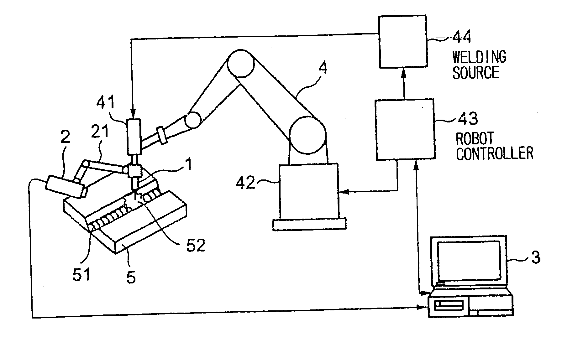
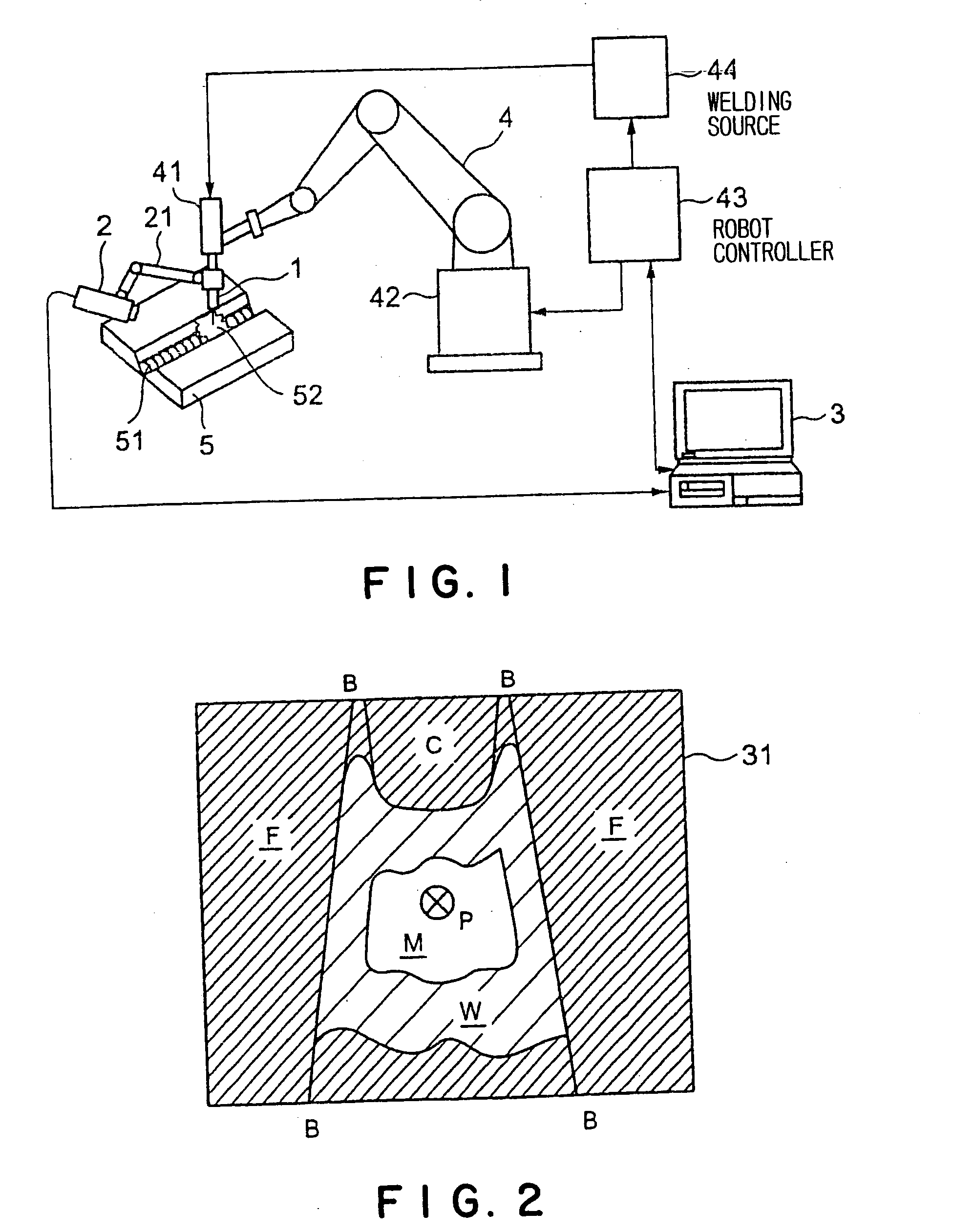
[0043]FIG. 1 is a block diagram of an automatic groove-tracing welding system in a first embodiment according to the present invention.

[0044] The automatic groove-tracing welding system in the first embodiment includes a welding torch 1, a camera head 2 combined with the welding torch 1, an image processor 3, and a welding robot 4. The welding robot 4 has an articulated robot arm 42 provided at its extremity with a robot hand holding a welding machine 41 provided with the welding torch 1, a robot controller 43, and a welding source 44 for supplying welding electric power to the welding machine 41.

[0045] The welding torch 1 is controlled according to a control program set beforehand for the welding robot 4 so as to move along a groove 51 formed in a workpiece 5 and to melt a welding wire to deposit a weld metal in the groove 51.

[0046] The camera head 2 provided with a CCD camera is attached to the free end of a support arm 21 fixed to the welding torch 1 suc...

second embodiment

[0110] Second Embodiment

[0111] An automatic groove-tracing welding system in a second embodiment according to the present invention is intended for application to arc welding using a nonconsumable electrode and a welding wire, such as TIG welding. The automatic groove-tracing welding system in the second embodiment is similar in construction, operation and effect to the automatic groove-tracing welding system in the first embodiment. The automatic groove-tracing welding system in the second embodiment has an additional function to correct the unsymmetry of the molten pool that occurs when weaving is not performed.

[0112]FIG. 12 is a block diagram of the automatic groove-tracing welding system in the second embodiment.

[0113] The automatic groove-tracing welding system in the second embodiment includes a welding torch 81, a welding wire feeder 83 that feeds a welding wire 82, a camera head 84 interlocked with the welding torch 81, an image processor 85, such as a personal computer, a...


PUM

PropertyMeasurementUnit
Fractionaaaaaaaaaa
Speedaaaaaaaaaa
Widthaaaaaaaaaa

Abstract

An automatic groove-tracing welding system is capable of carrying out a welding operation, particularly, a welding operation involving weaving, without requiring monitoring even if conditions of a groove is different from design conditions of the groove. An image processor 3 receives an image signal representing an image of a weld zone 52 including the tip of a welding wire from a camera head 2 provided with a CCD camera, processes the image of the weld zone 52 to determine the position of a groove, calculates the positional relation of the groove with a welding torch 1, and sends a position correction for correcting the position of the welding torch 1 so that the welding path of the tip of the welding torch 1 may coincide with a predetermined middle part in the groove to a robot controller 43 for controlling a welding robot. When the automatic groove-tracing welding system performs a welding operation involving weaving, the image processor 3 receives a weaving phase signal representing phases of weaving from the robot controller 43, calculates the positional relation between the groove and the welding torch on the basis of the phase of weaving, and sends a weaving width correction signal to the robot controller 43.

Description

TECHNICAL FIELD [0001] The present invention relates to an automatic groove-tracing welding method of welding workpieces along an actual groove on the basis of an image of a weld zone including the tip of the welding wire, and an automatic groove-tracing welding system for carrying out the same. The present invention relates also to an automatic welding machine capable of accurately carrying out groove-tracing welding involving weaving. BACKGROUND ART [0002] An automatic welding machine using a general-purpose robot or a welding robot is used for mass-producing standardized articles by welding and, in some cases, a weld monitor is used in combination with the automatic welding machine. The weld monitor takes the tip of a welding torch, and a weld zone including a molten pool with a camera head attached to the welding torch, and displays an image of the tip of the welding torch and the weld zone on the screen of a TV monitor. [0003] A technique disclosed in JP-A 11-146387 takes a wel...

Claims


Application Information

Patent Timeline
IPC IPC(8): B23K9/02B23K9/167B23K9/10B23K9/12B23K9/127B23K9/173
CPCB23K9/0216B23K9/1274B23K9/10
Inventor IIZUKA, TAKAHISAMIZUNO, HIDEAKIKINOSHITA, HIROKI
Owner KAWASAKI HEAVY IND LTD
Why Eureka
Try Eureka